Laboratory for orienting
single crystals
Jiří Hybler
CZ-18221 Praha 8, Czech Republic.
hybler@fzu.cz
Keywords: Laue method, single crystals, optical studies,
magnetic studies
Abstract
The study summarizes author’s
long experience with orienting single crystals used for optical and magnetic
studies.
Introduction
For various optical and
magnetic studies, single crystals in form of prisms, plates or other forms having
a defined orientation with respect to the crystal axes are required. In the
Institute of Physics of the Acad. Sci. of the Czech Republic, v.v.i., the
Crystal orientation laboratory belongs to the Department of Structure analysis,
and is located in the building Cukrovarnická 10, Prague 6. It is equipped with
the Oxford Diffraction X-ray stand, which has replaced in 2001 the aged
Mikrometa apparatus. The standard Chirana steel bar holder is still used for
attaching film cassettes and various kinds of crystal holders.
Experimental
The back-reflection
Laue method is a versatile method for aligning bulk crystals (attached on some
kind of a special holder allowing rotation and/or tilting to a certain extent)
in a desired position with respect to the crystallographic axes or planes. The
holder together with the oriented crystal can be then mounted onto the saw and
oriented specimens can be prepared by cutting. The back-reflection arrangement
allows checking crystals of a theoretically unlimited size. However, the
diffraction pattern represents the irradiated area only.
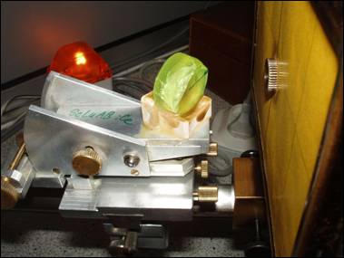
In the laboratory, two
kinds of holders are most commonly used; one of them allows tilting and
rotation around the vertical axis, both limited to less than approx. ±15˚ (Figure
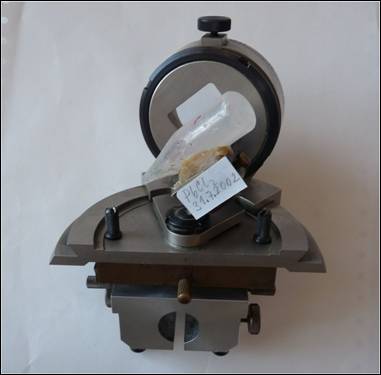
1). The second, with Eulerian geometry, allows full and partial rotation around
the χ and ω circles, respectively (Figure 2). The former holder
requires a crystal already pre-oriented by some other method, e. g. by the
light extinction between crossed polarizers. The Euler holder allows rotation in
a much wider range, but it can be mounted onto some kind of saw only.
The usual procedure involves
checking the crystal between crossed polarizers, then pre-orienting it with the
aid of the Eulerian holder, and finally setting it into an appropriate position
perpendicular to some important crystallographic plane with the aid of the tilt
and rotation holder. The oriented bulk crystal is then cut into smaller
oriented pieces, usually plates. These are returned to the laboratory and are
oriented along the second crystallographic plane. Then the cutting is repeated
and oriented specimens are prepared. Some faces may be polished if needed.
|
|
|
Figure 1. |
|
|
|
Figure
2. |
Interpretation
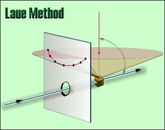
The unfiltered
(polychromatic) X-ray beam singled out by a collimator passes through the hole in
the film cassette and finally hits the stationary crystal. Diffracted beams are
recorded on a planar film. In our laboratory, a current Mo tube, producing
enough polychromatic radiation, is used. The Bragg condition is obeyed for an a
priori unknown wavelength corresponding to the given d and fixed ϑ
of the respective lattice plane. The geometric scheme of the method is in
Figure 3. Ordinary X-ray films are used for the recording.
|
|
|
Figure 3. Geometry of the back-reflection Laue method. (Source: http://www.matter.org.uk/diffraction/x-ray/laue_method.htm) |
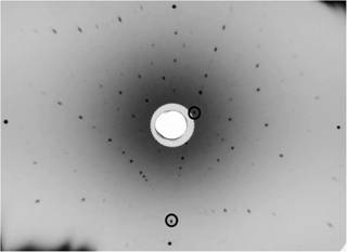
In Figure 4 there is an
example of a generally oriented Laue pattern with two prominent diffraction
spots, (indicated by circles). ¨
The method provides a
collapsed and distorted image of the reciprocal lattice [1], [2]. Diffraction
spots are arranged on garlands having the form of conic sections – ellipses and
hyperbolas for the front- and back-reflection arrangements, respectively. These
conic sections correspond to zones in direct space and planes in the reciprocal
lattice. The diffraction spots themselves correspond to reciprocal lattice
points, or to more than one point placed on the same radius vector in the
reciprocal space. The diffraction spots, where two or more hyperbolas cross are
usually intense and they are rather isolated from their neighbors. Usually they
represent reciprocal vectors corresponding to prominent crystallographic
directions. For more information, see also [3, 4]. Occasionally some
diffraction spot is excessively intense; in this case, the Bragg condition is
accidentally obeyed for the characteristic MoKα or MoKβ line.
|
|
|
Figure
4. Generally oriented
back-reflection Laue photograph with two possible prominent diffraction spots
(circled). |
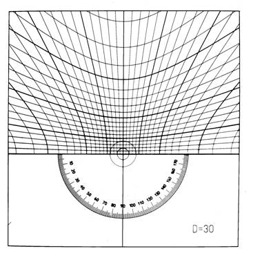
The respective angular
corrections are determined with the aid of the Greninger chart (Fig. 5). The
left-right hyperbolas correspond to the shape and position of garlands
depending on the angle made with the primary beam. The vertical hyperbolas
allow a determination of angles between the diffraction spots on hyperbolas.
When printed appropriately scaled, correct values can be read corresponding to
the sample-to-film distance of 30 mm. Note that the garlands (and respective
hyberbolas) closer to the origin are progressively flatter. In the extreme case
of the reciprocal lattice plane just parallel to the initial beam (and
perpendicular to the film), the hyperbola degenerates into a straight line.
|
|
|
Figure
5. Greninger chart for the
interpretation of back-reflection Laue photographs. The chart can be
downloaded from the page http://www-xray.fzu.cz/xraygroup/www/grchart.html |
The angular corrections
of the crystal mounted on the tilt and rotation holder are read as two
perpendicular coordinates of a selected diffraction spot with aid of the
Greninger chart. For the Euler holder, the crystal must first be set by
rotation of the χ circle to the equatorial plane, and then rotated by
ω circle into the appropriate position. After the corrections are done,
the selected reciprocal vector is just parallel to the primary beam and
perpendicular to the film. The corresponding crystallographic plane is parallel
to the film and perpendicular to the primary beam.
An aligned crystal
provides a diffraction pattern, where the distribution of diffraction spots and
of hyperbolas reflects the Laue symmetry around the axis parallel to the
primary beam. This arrangement is usually characteristic for the given
crystalline substance, orientation, and experimental conditions.
The final Laue
photographs are compared visually with a standard photograph of the same
compound from the author’s archive. If these standard lauegrams are not
available (for crystals not studied before) the following procedure is
performed: First, a small fragment is mounted on the Buerger precession camera
[5], aligned with the aid of the standard procedure for this method, then a
precession photograph is recorded, lattice parameters calculated and respective
reciprocal lattice vectors identified. Then the special back reflection
cassette is mounted on the precession camera, the motion is switched off, and
precession angle is set to 0. Under such conditions, a back reflection lauegram
is recorded. This photograph serves then as a standard for orientation of bulk
crystals. The procedure is then repeated for all necessary crystallographic
directions.
Examples of crystals studied
In the past decades
numerous oriented specimens of various crystalline compounds were prepared.
Some of them are listed here: PbCl2, PbBr2, PbWO4
(PWO), PbMoO4 (PMO), YAlO3 (YAP, Yttrium-aluminum
perovskite), LuAlO3, LiBaF3, LiCaAlF6, garnets
(YIG, LuAG, GGG), magnetite, LiYF4, LiLuF4, Lu2SiO5
(LSO), Y2SiO5 (YSO), (Lu,Y)2SiO5
(LYSO), CdWO4 and many others. In a small gallery, some
characteristic back-reflection Laue photographs are presented, with important
crystallographic planes (perpendicular to the primary beam) indicated (Figs.
6-9).
|
|
|
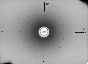
Figure
6. Lutetium-aluminum garnet,
Al5Lu3O12, cubic, (001), (fourfold axis), a*
and b* vectors indicated |
|
|
|
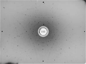
Figure
7. Lutetium-aluminum garnet,
Al5Lu3O12, cubic, (111), (threefold axis,
slightly misoriented). |
|
|
|
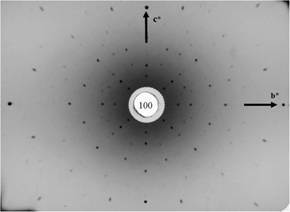
Figure
8. Lead tungstate PbWO4
(PWO, stolzite), tetragonal, scheelite structure, (100), (twofold axis). |
|
|
|
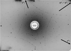
Figure
9. Lutetium silicate oxide Lu2SiO5,
(LSO), monoclinic, (010), (monoclinic twofold axis), a* and c*
vectors of two optional unit cells (C and I centered) are
indicated. |
Problems
Surfaces of crystals studied
Most of crystals studied
are artificially grown in the laboratory. Therefore they only rarely exhibit
natural crystallographic planes. Their shapes rather depend on the growth
method and/or previous cuttings. Most of crystals are Czochralski- or
Bridgmann-grown cylinders. While the former provides smooth surfaces well
suitable for X-ray diffraction, the surface of the latter is defined by the shape
of the ampoule and usually is matt, often with bubbles and is thus inappropriate
for diffraction in most instances. The currently used remedy is grinding and
polishing of a small plane in the appropriate area of the crystal prior the
diffraction experiment. In some instances (PbCl2) polishing provides
an excellent surface while in other materials it damages the near-surface zone,
affecting thus the quality of diffraction pattern.
Some crystalline
materials are covered by a nearly X-ray amorphous layer, well known examples
are gold and some intermetallic compounds.
Pseudosymmetry
Many structures are formally
derived by deforming some “ideal” type structure. Typical examples are
perovskites or closest-packed structures. Due to structural deformation, like
coordination polyhedra tilting (in perovskites) or unequal occupancy of holes
(in closest-packed structures) some symmetry elements are “lost”. As the real
atomic positions are still close to these of the “ideal” type structure, a
strong pseudosymmetry often persists. The diffraction images taken along the
“lost” and true axes are often very similar, so that they can be mismatched. The
Laue pattern must be very carefully checked in order to determine the true
symmetry.
For example, LiNbO3
represents rhombohedrally deformed perovskite [5]; only one of four triads of
the “ideal” cubic perovskite persists, similarly three of the six diads, but
none of the three tetrads. The α-Al2O3, (corundum)
is cubic closest packed structure rhombohedrally deformed due to partial
occupancy of Al in tetrahedral cavities. It also exhibits a significant
pseudosymmetry along “lost” axes of the non-standard F-centered rhombohedral cell.
CdWO4
(wolframite structure) is monoclinic, derived from the ideal tetragonal
structure. The a* and c* vectors correspond to tetragonal a*,
b* vectors and the preudosymmetry is so strong, that both directions
cannot be distinguished on the Laue pattern along b*. However, they can
be reliably distinguished on the h0l precession photograph,
because of the P2/c space group extinction (l=2n).
Crystal quality
Various physical
studies usually require crystals of certain degree of quality. This is not always
satisfied. Instead, many crystals are composed of mosaic blocks, which are in
some cases misoriented more than it is acceptable. If the crystal is carefully
oriented with respect to one given block, this orientation is not valid for the
rest of the crystal. In some cases such mosaicity can be revealed if the
primary beam just hits the domain boundary. In such a case the diffraction
spots are split, or even blurred, if there are several smaller domains in the irradiated
area. The mosaicity can sometimes be observed visually on the cleavage planes.
Twinning is another
complication which might appear. If the optical orientations of twin domains
are different, they can be recognized optically by observing the crystal
between crossed polarizers. The required oriented sample must be prepared from
one domain only.
Some compounds yield
Laue patterns with garlands sparsely occupied by diffraction spots. The interpretation
of such patterns is difficult, as the hyperbolas are not apparent at the first
glance, even if the crystal is close to the correct orientation. Magnetite, for
example, belongs to such problematic materials.
Ambiguity of unit cell choice
Many crystalline
compounds allow multiple unit-cell choices. For example, in the orthorhombic
system, 6 permutations of unit cell vectors are possible [7], producing up to 6
possible space group symbols. In monoclinic crystals, alternative I- or C-
centered unit cell choice might appear. As the researchers from other branches
of physics and chemistry are usually not well trained in crystallography, they
might mismatch crystal directions. A deplorable, but unfortunately very common
practice is referring values of physical measurements with respect to
crystallographic directions, without specifying the unit cell.
Ambiguity of modification
Some chemical compounds
exist in more than one crystallographically distinct modification. In physical
journals, authors sometimes forget to specify to which modification the values
in the given paper refer. This fact represents another possible source of
confusion. If there is any doubt about the modification of the crystal studied,
a small fragment should be tested on a precession camera or a diffractometer.
References
1. Amorós,
J.L., Buerger, M.J., Amorós, M.C. de: The Laue Method. New York-San Francisco-
2.
3. Ďurovič, S., Hybler, J.: Monokryštálové
filmové metódy. Sborník: Experimentální techniky v rentgenové a neutronové
strukturní analyze, Krystalografická společnost 1994 (in Czech and
Slovak).
4. Hybler, J.: Monokrystalové metody
s registrací na film nebo obdobná plošná media. On the webpage: http://www.xray.cz/kryst/difrakce/hybler/monokrystal.htm
(in Czech).
5. Buerger, M.J.: The Precession Method in X-ray
Crystallography. New York-London-Sydney 1964, John Wiley & Sons.
6. Vokoun, J., Studnička, V.: Hodnocení základních materiálů elektroniky použitím rtg metod.
Výzkumná zpráva č. 1620 13 712/3, TESLA VÚST A.S.Popova, Praha 1982. (In Czech)
7. Hybler, J.: The permutations of lattice
parameters and space group symbols of the orthorhombic PbCl2. Cryst.
Res. & Technol. 23, 1127-1133, 1988.
Acknowledgements.
Single crystals
for studies were kindly provided by M. Nikl and K. Nitsch from the Institute of
Physics, Acad. Sci. of the Czech republic, v.v.i. I also thank M. Rieder for
critically reading the text.