Neutron Diffraction Study of Residual Stresses in Engineering Components formed via Additive Manufacturing
G. Németh1, R. Kocich2, M. Benč2
1Nuclear Physics Institute, 25068 Řež near Prague, Czech Republic.
2Faculty of Materials Science and Technology, VŠB-Technical University of Ostrava, 708 00 Ostrava, Czech Republic
Additive manufacturing (AM) technique enables us to build three-dimensional complex engineering parts without the use of expensive tools such as casting molds, dies or punches. However, large thermal gradients appear during the process [1] which may give rise to anisotropy of the structure and consequently to residual stresses (RS). Neutron diffraction (ND) strain scanning is a powerful technique to study the distribution of RS non-destructively. Two samples from ASI 316 steel, prepared by AM, were subjected to linear ND strain scans with three mutually perpendicular orientations of the diffraction vector. In the case of the complex shape-sample 1 (CS) (Figure 1.), the tip was scanned. In the case of a cylinder-sample 2 (with diameter 10.25 mm after additional swaging), four scan-lines mutually rotated by 45°, lying in the cross section of the cylinder, were applied (Figure 2.).
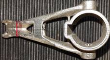
Figure 1. Complex shape sample 1 and Figure 2. Cylinder and the scanned lines
the scanned line (red) (yellow)
However, the measured data had to be corrected due to pseudo-strains caused by beam attenuation and by partial immersion of sampling volume in the sample near the edges [2]. Since the stress-free reference was unavailable, the absolute stress differences and then the Von Mises (VM) equivalent stresses were evaluated from the reconstructed two theta distributions [3]. The VM stresses provide valuable information about the overall RS state of the measured regions. According to this, the tip of the CS sample exhibits the largest RS 3-5 mm beyond the edges, where the arms connect to the tip. The maximum VM stress in these regions were 100-120 MPa. In the case of sample 2, RS distribution maxima are mainly located near surface regions (Figure 3.) however, the center region also shows larger RS. The distribution roughly maintains the axial symmetry of sample 2. Areas with increased VM stresses are closer to the yield point.
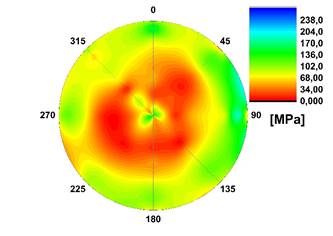
Figure 3. VM stress distribution in the cross section of cylinder-sample 2
[1] T. D. Ngo, A. Kashani, G. Imbalzano, K. T. Q. Nguyen, D. Hui, Composites Part B-Engineering 143 (2018) 172-196
[2] J. Šaroun, J. Rebelo-Kornmeier, J. Gibmeier, M. Hofmann, Physica B: Condensed Matter 551 (2018) 468-471
[3] P. Strunz, R. Kocich, D. Canelo-Yubero, A. Macháčková, P. Beran, L. Krátká, Materials 13(12) (2020) 2869.