Lattice parameters from electron diffraction: vain(?) struggle against image distortions
L. Palatinus, P. Brázda, Y. Krysiak
Institute of Physics of
the CAS, Na Slovance 2, Prague 8, Czechia
palat@fzu.cz
Transmission electron microscope is an electron optical system. The imperfections of its elements introduce aberrations in the images obtained by the TEM. In electron diffraction experiments, the main concern is about the geometrical distortions that change the positions of the objects in the image. These geometrical distortions cause the shift of the positions of the recorded reflections, leading to problems in the analysis of the diffraction data, in particular in the determination of lattice parameters of the investigated material.
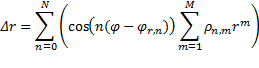
To characterize the distortions in a general manner, we expand the geometrical distortions into a series of circular harmonics. Be (x,y) the undistorted coordinates in the diffraction pattern and (x’, y’) the distorted coordinates (Fig.1), then we define the relationship as:
![]()
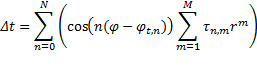
![]()
where Δr and Δt are the radial and tangential components of the distortion, and are parameterized in terms of the polar coordinates r, φ of the point (x,y) (Fig. 1):
And ![]() ,
, ![]() ,
, ![]() and
and ![]() are the parameters of the
distortions. Such an expansion includes naturally all commonly known
geometrical distortions like the spiral, barrel-pincushion or elliptical
distortion (Fig. 2) but it includes also other distortions.
are the parameters of the
distortions. Such an expansion includes naturally all commonly known
geometrical distortions like the spiral, barrel-pincushion or elliptical
distortion (Fig. 2) but it includes also other distortions.
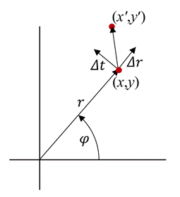
Figure 1. Decomposition of the distortion vector into radial (Δr) and tangential (Δt) components.
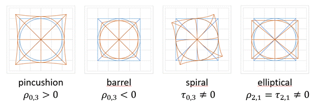
Figure 2. Examples of the typical distortions. Each figure shows, how the distortion deforms an object composed of a square, circle and a cross. Undistorted object in blue, distorted object in orange. Label below the figure is the name usually given to this distortion. The lower line indicates, which coefficient of the general expansion are non-zero for each distortion.
Traditionally,
the distortions are determined by recording a single oriented diffraction
pattern of a known material and comparing the recorded reflection positions
with the expectation. However, such a measurement provides only a limited
amount of data and limited accuracy. Instead, we use a full 3D electron
diffraction (3D ED) data set, which typically comprises over a hundred
diffraction patterns recorded at a range of orientations of the crystal [2].
The refinement of distortions against such data yields an unprecedented
accuracy of the determined distortion coefficients. We can distinguish three
cases:
• Known lattice parameters, unknown distortion
coefficients: In such a case the distortion coefficients can be determined with
very good accuracy. These coefficients can be then used in the analysis of
other data sets. Refinement of the distortion coefficients also proved a better
prediction of reflection positions on the diffraction images, leading to a more
accurate intensity extraction.
• Unknown lattice parameters, known
distortion coefficients: The lattice parameters can be refined against
reflection positions corrected for the (previously determined) distortions. The
accuracy of the lattice parameters is then dramatically improved (see below).
• Unknown lattice parameters, unknown
distortions: This is the most complicated situation and in the most general
case it is not possible to refine reliably the lattice parameters and
distortion coefficients simultaneously. The correlations can partly be
suppressed by using the information about lattice symmetry (i.e. Bravais
class), or by combining data from more than one crystal.
The
parametrization of the distortions and the refinement of the distortion
coefficients was implemented in the computer program PETS for analysis of 3D ED
data [3]. As illustrated in Table 1, the use of distortions in the refinement
of the lattice parameters can dramatically improve the accuracy of the lattice
parameters as well as the accuracy of the prediction of the reflection
positions.
Table 1: Lattice parameters obtained with three different approaches to the refinement. RMSD is the root mean square deviation (in reciprocal Angstroms) of the predicted and measured reflection positions.
|
|
a |
b |
c |
α |
β |
Γ |
RMSD |
|
Known and fixed lattice parameters, no
distortions |
8.369 |
10.721 |
5.115 |
90 |
90 |
90 |
0.0108 |
|
Unrestrained cell refinement, no distortions |
8.266 |
10.600 |
5.155 |
89.948 |
90.050 |
89.473 |
0.0050 |
|
Unrestrained cell refinement, optimized
distortions |
8.352 |
10.743 |
5.115 |
90.01 |
90.00 |
89.85 |
0.0041 |
1. Capitani et al., Ultramicroscopy 106, (2006), 66-74
2. Gemmi, et al., ACS Cent. Sci. 5, (2019), 1315-1329
3. Palatinus et al., Acta Crystallogr. B 75, (2019), 512-522
This
research was supported by the Czech Science Foundation, project number
19-08032S.