Study of the real structure of the laser-cladded steel
Karel Trojan1, Václav Ocelík2, Jiří Čapek1 and Nikolaj Ganev1
1Department of Solid State Engineering, Faculty of Nuclear Sciences and Physical Engineering, CTU in Prague, Trojanova 13, 120 00 Prague 2, Czech Republic
2Department of Applied Physics, Zernike Institute for Advanced Materials, Faculty of Science and Engineering, University of Groningen, Nijenborgh 4, 9747 AG, Groningen, The Netherlands
AISI H13 hot working tool steel is one of the most common die material used in metal and casting industries. Dies suffer damage due to wear and thermo-dynamic stresses during their lifetime [1]. Therefore, various methods have been developed for their repair, which is cheaper than manufacturing new ones. A great benefit of laser cladding in this field is a high productivity with minimal influence due to a low heat input on surrounding material by thermal stresses [2]. Therefore, the aim of the contribution is to describe the effects of laser processing on the microstructure of laser cladded H13 tool steel using orientation imaging microscopy (OIM) based on electron backscatter diffraction (EBSD) and other techniques.
Laser cladding was carried using an IPG 3 kW Yt:YAG fibre laser. The laser power density of 114 J/mm2 was applied to form a volume consisting of five overlapping layers, see Fig. 1. The martensitic structure was observed on the cross-section of the clad using electron backscattering diffraction, see inverse pole figures (IPF) of ferritic phase in Fig. 2. The original austenite grains with a characteristic size of 20–50 µm, which were formed during the transition of the melt into a solid phase and whose were subsequently transformed into martensitic or bainitic laths, are clearly seen in the figure. It has to be noted that the EBSD technique is not able directly distinguish ferrite and martensite.
Further, the clads were subjected to X-ray diffraction measurement, tensile testing, wear resistance and hardness measurement for comprehensive utilization evaluation of laser cladding.
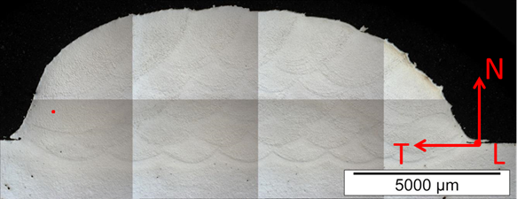
Figure 1: Metallographic cross-section of the clad AISI H13 tool steel with marked directions and area which was observed using OIM.
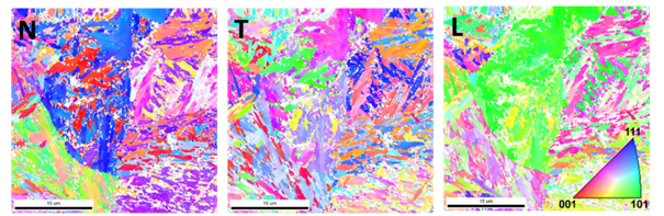
Figure 2: IPF maps of ferritic phase for different directions in the selected area, where N, T, and L denote the directions.
Measurements were supported by the project TH02010664 of the Technology Agency of the Czech Republic and by University of Groningen. This work was supported by the Grant Agency of the Czech Technical University in Prague, grant No. SGS19/190/OHK4/3T/14.