New knowledge of the texture and structure evaluation by EBSD method
M. Černík, P. Vranec, A. Drotár, A. Mašlejová
1U.S.Steel Košice, s.r.o., Vstupný areál U.S. Steel, 044 54 Košice
mcernik@sk.uss.com, pvranec@sk.uss.com, adrotar@sk.uss.com, amaslejova@sk.uss.com
Method of electron diffraction referred to by EBSD acronym (electron back-scattered diffraction) has been used mainly for the analysis of the textures of polycrystalline materials until recently. With the development of new powerful detectors and software this method allows the study of microstructure. Comparing to the microstructure investigation by light microscope, the microstructure obtained by EBSD method is precisely defined by image gained from the Kikuchi lines. Therefore, it is possible to determine phase composition of the sample, grain boundaries, their size, misorientation etc. Inaccuracy of the method is given by inaccurate determination of the crystallographic orientation from the Kikuchi lines image or imperfect sample preparation. Sample preparation is therefore highly important and demand experience. The preparation is related to the investigated material type and state and is always unique. Generally, there are three ways of sample preparation for EBSD: mechanical polishing, electrolytic polishing and ion bombardment or their combination.
It is possible to study the texture of rolled steel strips by EBSD method, which is also able to be investigated using X-ray diffraction (XRD) device with texture goniometer. Each method has its advantages and disadvantages. Highly deformed samples are hard to prepare for the EBSD, therefore it is better to analyze such samples by X-ray texture analysis. However, there are steel grades which have very big grain and it is difficult and almost impossible to analyze them by X-ray diffraction method, which uses focused beam with the radius of 1 mm. In this case it is effective to use EBSD method and scan whole area of the sample section (standardly 25 x 0.5 – 1.0 mm). Usually it is more than 100 scanned images – Inverse Pole Figure maps (IPF maps).
Second area of investigation where the EBSD method is successfully applied is identification of microstructure for transformed induced plasticity (TRIP) steels. Structural composition – bainite, martensite, ferrite and retained austenite is determined. After mechanical polishing the sample is polished electrolytically in the solution of electrolyte containing acetic and perchloric acids. The quality of the sample preparation can be evaluated by zero solution parameter, i.e. percentage of unmeasured spots, pixels (ZS). ZS value of 0 is practically unreachable because it is impossible to precisely determine orientation at the grain boundaries. ZS values of 2 – 4 % can be considered as acceptable for obtaining correct result. The volume of retained austenite is able to be identified for occurrence of min. 5 %, what is better than ability of determination by XRD. Determination of the martensite and bainite volumes is not possible from the Kikuchi lines image due to the fact that the tetragonality of the martensite is too small. The differentiation of the martensite and bainite from the ferrite is possible only based on the signal from the EBSD camper, using the Image Quality (IQ) Map.
The EBSD method can be also used for the evaluation of the state of alloyed (C, Cr, Mo, V) hard and fragile steel components. The structure contains carbides (Fe3C, Cr7C3), complex sulfides (MnS). It is highly probable that due to the formation of grown carbidic and sulfidic particles these can act as initiators of microcracks. These particles are fragile and at the increased pressure they crack, what forms initiation of the microscrack, which will under the regular load spread by fatigue mechanism. For such materials it is possible to use parameter of Misorientation. By suitable selection of the parameters (7x7 pixels) it is possible to form microstress map which shows microstress on the crystallographic grains level. Using function of strain contouring which uses also parameter of misorientation, it is possible to show microstress through the whole investigated component, what allows study of the microscrack spreading in the material, see Fig. 1.
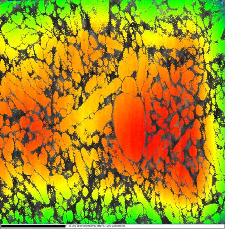
Figure 1. Strain contouring map of roller. Chromium steel with particles.