Structure,
microstructure and residual stresses in borided
steels
Z. Pala1,
R. Mušálek2, J. Kyncl3, P. Harcuba4, J. Stráský4 , K. Kolařík1
1Department of Solid State
Engineering, Faculty of Nuclear Sciences and Physical Engineering, Czech
Technical University in Prague, Trojanova 13, Prague,
Czech Republic
2Department of Materials Engineering,
Institute of Plasma Physics, Za Slovankou 1782/3, Prague, Czech Republic
3Department of machining, process
planning and metrology, Faculty of Mechanical Engineering, Czech Technical
University in Prague, Technická 4, Prague, Czech
Republic
4Department of Physics of Materials,
Faculty of Mathematics and Physics, Charles University in Prague, Ke Karlovu 5, Prague, Czech
Republic
zdenek.pala@fjfi.cvut.cz
Keywords: boriding,
surface hardening, iron borides, tooth-shaped microstructure, residual
stresses.
Boriding
or boronizing belongs to thermo-chemical diffusion-based
surface hardening of iron materials.
Even though it is comparatively rarely applied in industrial processes
in comparison with other treatments, it can lead to substantial increase of
service life, especially when extreme wear occurs on the surface. The main
virtues of borided surface are not only the high
hardness surpassing in some cases even 2000 HVN (Vickers hardness number), but
also very low friction coefficient and above-average resistance to an array of
acids and to high-temperature oxidation in a broad range of temperatures from
ambient up to approximately 1000 °C. For example, the intrinsic hardness of Fe2B
is 1700 HVN or by order of magnitude higher than of pure iron
with 130 HVN [1]. In general, whereas boriding leads
to 1500 to 2000 HVN, the most widely applied treatments of nitriding
and carburizing lead to 600 ÷ 1100 HVN and 700 ÷ 850
HVN, respectively [2]. At the same time, borided
layers exhibit high thermal and electrical conductivity which can be an asset
when compared with e.g. ceramic wear protective layers. Probably the main advantage
of the borided process is such that it imposes
virtually no limitations of the shape of the borided
object, since the boron sublimates at higher temperatures from the boron source
(typically powder) adjacent to the borided surface
and penetrates into it via diffusion mechanism.
Both the boriding process and the structure of the resulting zone
consisting of borided layers, base material and the
interface in between them are intriguing since the complete description of the boriding mechanism is still lacking. Moreover, the
structural phenomena involved encompass not only two distinct crystalline
phases of tetragonal Fe2B, which has three polymorphs with space
groups I-4/mcm or I-42m, and orthorhombic FeB (Pbnm), but also substantial residual stresses differing
both in values and even character in both phases and with appreciable stress
gradient, texture is often present and also grain boundaries represent a fairly
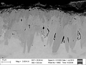
complex structural issue. From the microstructural point of view, the interface
between the borided layers and base material is
commonly described as having “tooth-shaped” or “saw-tooth” character as seen in
Fig. 1. The spatial layout of the phases is usually such that FeB is on the surface and the needles in deeper layers are
grains of Fe2B. Consequently Fe2B layers tend to exhibit
higher degree of preferred orientation, most commonly ![]() fibre texture [3], yet texture of FeB
layers is no exception. Since FeB is the brittler phase, the single phase borided
layer of Fe2B with good toughness is usually preferred to the duplex
phase Fe2B
+ FeB layer . Moreover, since the FeB
is distinguished by almost triple value of thermal expansion coefficient when
compared with the base material, it usually decomposes from the borided object during cooling after the boriding
process, which is described as thermo-mechanical spalling.
fibre texture [3], yet texture of FeB
layers is no exception. Since FeB is the brittler phase, the single phase borided
layer of Fe2B with good toughness is usually preferred to the duplex
phase Fe2B
+ FeB layer . Moreover, since the FeB
is distinguished by almost triple value of thermal expansion coefficient when
compared with the base material, it usually decomposes from the borided object during cooling after the boriding
process, which is described as thermo-mechanical spalling.
In general, there are two parameters of borided surface which are being optimized via the boriding process conditions. Firstly, the effort is aimed at obtaining such microstructural morphology that would lead to better toughness and ductility coupled with sufficient adhesion of the borided layers facilitated by the tooth-shaped interface. Secondly, the spatial distribution of macroscopic residual stresses in the borided layers and the adjacent area of substrate should be such that would favour good cohesion within the hard layers and also contribute to the adhesion of the surface to the bulk.
|
|
|
|
Figure 1. “Tooth-shaped” microstructure of borided layers created in the surface of hard-to-work chromium ledeburitic steel X210Cr12 after 5 hours (left) and 12 hours (right) of boriding at 930 °C in powder. |
|

The
existence of texture significantly hinders the calculation of residual stresses
in iron borides, especially in Fe2B. So far, the texture was omitted
in the calculation of residual stresses and we are currently developing an algorithm
to take the effect of texture into account. In order to do this, single crystal
elastic constants have to be known. There have been several attempts to
calculate them using DFT (Density functional theory), but the results differ by
as much as 100 %. Hence, residual stresses are calculated with macroscopic, or
bulk, elastic constants in the generalized Hooke equation which can bring about
unreliable results.
The
aim of the hitherto carried out analyses was to ascertain whether boriding can bring beneficial effects to highly alloyed hard-to-work
chromium ledeburitic steel X210Cr12 suitable for cold
forming tools. The high levels of carbon (1.9 ÷ 2.2 wt%), silicon (0.1 ÷ 0.6 wt%) and especially chromium (11 ÷ 13 wt%) have so far rendered the boriding infeasible. This material is a
standard for silica and alumina pressing tools or moulds which also explains
the practical necessity to improve its wear resistance. Pursuing this aim, the real parts of pressing
mould were borided for 5 and 12 hours, respectively.
The resulting objects with borided surfaces were
examined by SEM (Scanning electron microscopy), phase composition and residual
stresses were determined from X-ray diffraction and microhardness
was measured on the cross-section of the samples by Vickers indentor.
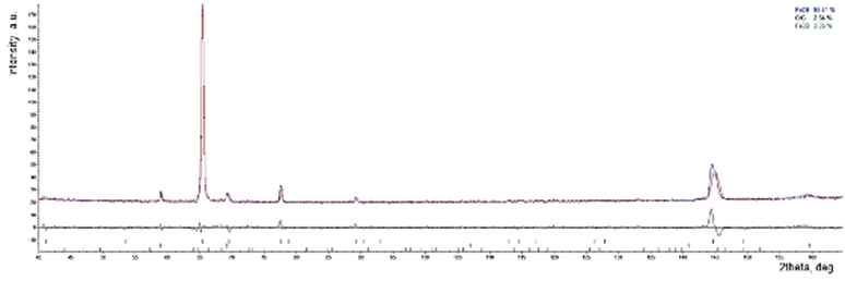
Figure 2. Result of Rietveld refinement
showing dominant presence of Fe2B, in order to take texture into
account, March-Dollase metod was employed. The macroscopic residual stresses
were not considered, hence the shift of modelled date at higher 2θ at
145°.
Micrographs
from SEM revealed than the prolongation of processing time had only marginal
effect on the borided layer thickness, increasing
from approximately 30 to 40 μm. However, the
important difference between both microstructures (see Fig. 1) is the change
from duplex to almost single phase. This was verified by X-ray diffraction (CrKα radiation) when the diffraction patterns were
obtained on the original free-surfaces and in depths of 10 and 20 μm. Phase identification revealed presence of both Fe2B
and FeB on the surface of 5h borided
sample, but only FeB on 12h borided
one. Both surfaces included also phases of iron borate Fe3BO5.
After electro-chemical removal of 20μm thick surface layer, only Fe2B
was found in both samples; the 12h sample included also minor phase of CrC and Fe3B while the 5h sample contained CrC, Cr7C3 and Fe23(C,B)6. Rietveld refinement
of the 12h sample showed about 93 wt.% of Fe2B
as seen in Fig. 2, the comparatively bad match between the measured and modelled
data at 145 °2θ is clear evidence of macroscopic residual stress presence
which were not considered in this refinement. The most pronounced diffraction
peak in Fig. 2 is from CrKα diffraction on
textured (002) planes of Fe2B and were the irradiated volume without
preferred orientation this peak would have 25% relative intensity of (211) peak
at approximately 70 °2theta.
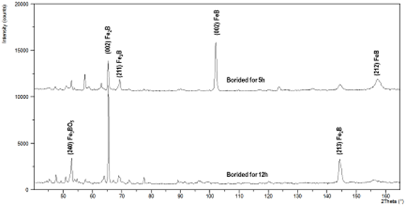
Figure 3. Comparison of diffraction patterns
obtained on the surfaces of both samples.
Mutual
comparison of diffraction patterns obtained at the surface of both samples is
in Fig. 3. Measured values of microhardness in the borided layers were surprisingly small, i.e. 1350 ± 180 HVN
and 1520 ± 220 HVN for 5h and 12h samples, respectively. The correct
calculation of residual stresses was possible only for FeB,
where (212) planes were measured in various orientations to the surface taking
advantage of the so-called omega geometry. The resulting dependence of inteplanar lattice spacing versus sin2ψ was
linear and the calculated value of macroscopic residual stress was
approximately -300 MPa as seen in Fig. 4.
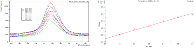
Figure 4. Measured diffraction profile of
(212) planes of FeB (left) and 2θ vs. sin2ψ dependence
from which the value of macroscopic residual stress was calculated.
References
1. C.T.Zhou, J.D. Xing, B.Xiao, Comp. Mat. Sci., 44, (2009),
1056-1064.
2. P. Gopalakrishnan,
P. Shankar, M. Palaniappa, Met. and
Mat. Trans. A, 33, (2002), 1475-1485.
3. R. Prűmmer, W.
Pfeiffer, J. Less-Common Met., 117, (1986), 411-414.
Acknowledgements.
This
research was carried out in the frame of research projects TA02011004
(Technology Agency of the Czech Republic).