Cylindrical
image plate diffractometer – orienting and indexing of large compact samples
in reflection mode
Z. Matěj1, J. Šmilauerová1, J. Pospíšil1,
T. Brunátová1, P. Harcuba1, V. Holý1,
R. Kužel1
1Faculty of Mathematics and Physics,
Charles University in Prague,
Ke Karlovu 5, 121 16 Praha 2, Czech Republic
matej@karlov.mff.cuni.cz
Introduction
Rigaku RAPID II
installed in the X-ray lab at MFF UK [1] is a versatile diffractometer
proposing diverse options for material analysis by X-rays. It is equipped with a
three-axis goniometer and a large curved image plate (IP) detector. The
instrument can be routinely utilised for single crystal structure solution as
well as for powder diffraction. Residual stress or texture studies were also reported [2].
The aim of this contribution is a discussion of possibilities and limitations
of this instrument, which is not as common as the Bragg-Brentano or parallel
beam diffractometers. Its unique advantage, that large parts of the reciprocal
space are explored simultaneously, is illustrated on an example application of
the analysis of (coherent) inclusion nanoparticles in Ti-alloys.
|
|
|
|
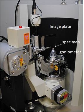
Figure 1. Rigaku R-Axis Rapid II diffractometer with
image plate system. |
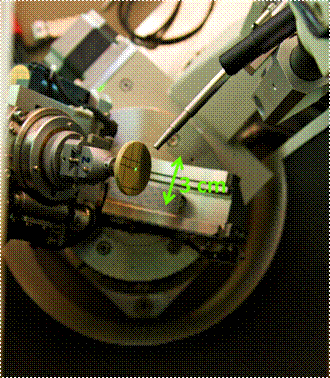
Figure 2. Florescent target mounted in the sample position.
During a typical experiment two goniometer axes are set to fixed positions (omega = 210°, psi = 55°) and the sample is
spinning/oscillating around the axis (phi)
perpendicular to the sample surface. |
Diffractometer,
large samples and reflection geometry
The
diffractometer is depicted in Fig. 1. Its standard applications include
analysis of small (~ 0.01-1 mm) single crystal samples or powders filled in glass/capton
capillaries. These experiments can be done directly in transmission geometry
and the advantage of the large cylindrical IP detector to capture a wide
range (~ 200°) of
scattering angles is fully utilised. Contrary, for large (~ 10 mm) compact samples of
a “coin” size and thickness, which are of main interest here, the
reflection geometry is the only reasonable option. A typical experiment is
depicted in Fig. 2. The sample surface is roughly aligned to be
perpendicular to the (phi) spin axis.
Other two goniometer axes (omega, psi) are set to general fixed positions.
A quick (20-30 min) “survey” experiment can be done with sample (phi) spinning or a series of pictures
can be acquired with crystal oscillating in small (phi) intervals during an “overnight” experiment.
|
|
|
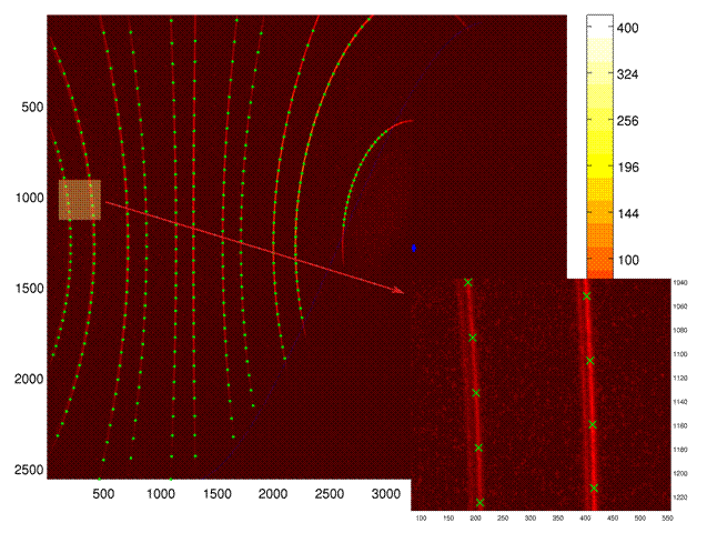
Figure 3. Analysis of Debye rings from the NIST standard Si
powder sample for calibration of beam and sample displacement instrumental
corrections. Diffracted intensity in the bottom right corner of the IP is
shadowed by the goniometer head. |
Reference
samples
In order to
understand the diffraction geometry in detail and test the accuracy of the
experiment the NIST standard Si powder sample and a high quality defect free Si
wafer were measured under conditions described above. The analysis of the Debye
rings from the powder sample is illustrated in Fig. 3. In the first step
diffracted intensity at several (beta)
positions on the rings was fitted with Cu-Kalpha doublet profiles. The refined
experimental 2Theta positions were then
compared with that calculated for the nominal lattice parameter and including
zero-beam and sample displacement [3] corrections. This difference was smaller
than ~ 0.05° on all the Debye rings. If in addition the lattice parameter
was refined, the discrepancy from the nominal value was about ±0.001 Å.
For single crystal data the accuracy reached was slightly worth. About 15-40
diffraction maxima were analysed. The differences in 2Theta positions were practically same ~ ±0.05° and the (beta) positions on the rings were
predicted with ~ 0.1° error. Unfortunately the discrepancy in the lattice
parameter was ±0.003 Å for the single crystal experiments.
|
|
|
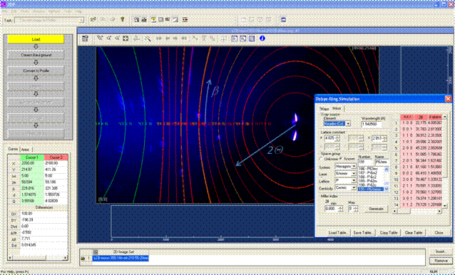
Figure 4. A preliminary analysis of the quick “survey”
measurement of the LCB beta-Ti alloy single crystal using the Rigaku 2DP software. Simulated green Debye
rings are related to the (bcc) beta-Ti matrix phase. Contrary red lines come
from the minor omega-Ti nanoparticles. The lattices of both phases are
coherent hence some beta-Ti green rings are overlapped with red rings of
(hexagonal) omega-Ti. |
Orienting and
indexing of single crystals of LCB Ti-alloy
Indexing of
LCB beta-Ti alloy [4] is a challenging problem. The single crystals
consist of a metastable bcc beta-Ti matrix and of a large fraction of
(coherent) inclusion nanoparticles of hexagonal-Ti. The samples were analysed
also by pole figures (PF) measurements and reciprocal space mapping in [5].
A preliminary
analysis of the quick “survey” experiment using the Rigaku 2DP software is
depicted in Fig. 4. Diffraction maxima from two different crystal systems
(bcc beta-Ti matrix and inclusion of hexagonal omega-Ti phase) are simply
identified. A large part of the reciprocal space is examined in this rapid
experiment. This is an advantage especially if we consider that e.g. for PF
measurements the line (2Theta)
position must be known a priory. The longer “overnight” experiments
brilliantly simplify the orientation and indexing procedures and enhance signal
from weak diffraction maxima. An image from such a measurement is depicted in
Fig. 5. Finally it was indexed by the beta-Ti matrix and four families of
omega-Ti inclusions [5].
|
|
|
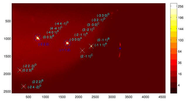
Figure 5. Possible indexing of an image taken in the
oscillation mode. Intensity maxima can be indexed by (bcc) beta-Ti matrix
(blue circles) and by 4 families (subindexes A, B, C, D) [5] of
(hexagonal) omega-Ti (cyan crosses). |
References
1. R. Kužel, Rigaku R-Axis Rapid II at MFF UK: http://www.xray.cz/kfkl-osa/eng/rapid/
(Jul 23, 2013).
2. M. Gelfi, E. Bontempi,
R. Roberti, L.E. Depero, Acta Mat., 52, (2004), 583.
3. N. V. Y. Scarlett,
M. R. Rowles, K. S. Wallwork, I. C. Madsen, J. Appl. Crystallogr., 44, (2011), 60-64.
4. J. Šmilauerová,
J. Pospíšil, J. Cryst. Growth,
(2013), submitted.
5. V. Holý, J. Šmilauerová,
J. Stráský, J. Pospíšil, M. Janeček, Mat. Struct. Chem. Bio. Phys. Tech., 20, (2013),
a contribution in these proceedings.
Acknowledgements.
This
work has been supported by the Grant Agency of the Czech Republic (project no.
P108/11/1539) and within the Charles University Research Center “Physics of
Condensed Matter and Functional Materials” (no. UNCE 204023/2012).