Study of zirconium base alloys by neutron diffraction
M. Krůželová1, S. Vratislav1,
M. Dlouhá1
1 Department of Solid State Engineering, FNSPE, CTU, Trojanova 13, 120 00, Prague 2, Czech Republic
monika.kruzelova@fjfi.cvut.cz
Introduction
Neutron diffraction is a very powerful tool in texture analysis of zirconium base alloys used in nuclear technique [1]. Textures of five samples (two rolled sheets and three tubes) were investigated by using direct pole figures, inversion pole figures.
The texture measurements were performed at diffractometer KSN2 at Laboratory of Neutron Diffraction, Department of Solid State Engineering, Faculty of Nuclear Sciences and Physical Engineering, CTU in Prague. The wavelength used was λ = 0.1362 nm. The data were processed using software packages HEXAL [2] and GSAS [3].
Basal pole figures
Basal pole figures were measured for samples Zr1,
Zry2, and ZiT [4] (Fig. 1).
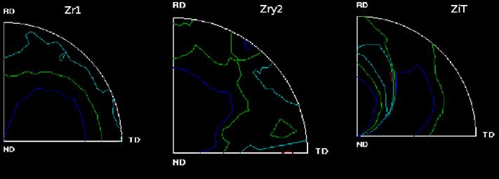
Figure 1. Comparison of basal pole figures of
zirconium samples Zr1, Zry2, and Zit. System of coordinates is represented by
ND, RD, and TD
Inverse pole figures
Inverse pole figures were calculated for samples Zrp, Zry2, ZiT, and ZrW. The intensity ratios were calculated by Mueller formula [5]. Calculated inverse pole figures are at Tab. 1 [4]. The intensity ratios are relative to the non-texture stage.
Table 1. Calculated inverse
pole figures of samples Zrp, Zry2, ZrW, and ZiT.
|
Sample |
p002,
ND |
p002,
(0,45) |
p100,
RD |
p100,
TD |
p110,
RD |
|
Zrp |
3.076 |
N |
2.742 |
1.173 |
1.678 |
|
Zry2 |
1.702 |
1.729 |
1.173 |
0.886 |
2.780 |
|
ZiT |
1.158 |
1.807 |
3.767 |
0.747 |
0.719 |
|
ZrW |
1.170 |
2.403 |
2.951 |
0.444 |
0.788 |
Discussion and Conclusions
Our results can be summarized as follows:
All samples of zirconium alloys show the distribution of middle area into two maxims in all basal pole figures. This is caused by alloying elements. A characteristic split of the basal pole maxima tilted from the normal direction toward the transverse direction can be observed for all samples.
·
Sheet samples prefer
orientation of planes (100) and (110) perpendicular to rolling direction and
orientation of planes (002) perpendicular to normal direction.
·
Basal planes of tubes
are oriented parallel to tube axis; meanwhile (100) planes are oriented perpendicular to tube axis.
·
Level of resulting
texture and maxima position is different for tubes and for sheets.
Zirconia-based alloys are used in nuclear technology, and
our results are consistent with data published by other authors [6].
References
1. G. E.
Bacon, Neutron Diffraction, 3rd
ed., Oxford: Clarendon Press, 1975.
2. M. Dlouhá, L. Kalvoda, S. Vratislav, B. Čech, Texturní analýza trubek ze zirkoniových slitin neutronovou difrakcí, Kovové materiály 4.29, Bratislava, 1991.
3. A.C. Larson, R.B. Von Dreele,
General Structure Analysis System (GSAS), Los Alamos National Laboratory
Report LAUR 86-748, 1994.
4. M. Krůželová, Studium vlastností slitin na bázi
zirconia metodou neutronové difrakce, Diplomová práce, české vysoké učení
technické v Praze, Fakulta jaderná a fyzikálně inženýrská, Katedra inženýrství pevných látek, 2010
5. R. M. S. B. Horta,
W. T. Roberts, D. V. Wilson, Texture
representation by inverse pole figures, Technical report, TMS - AIME, 1969.
6. A. V. Nikulina, Zirconium Alloys in Nuclear Power
Engineering, Metal Science and Heat Treatment,
46, 2004, pp. 458 - 462