Analysis of highly mobile twin boundary in NiMnGa martensite by X-ray
diffraction
J. Drahokoupil1 , L. Straka2, O. Heczko1
1Institute of Physics of the
ASCR, v.v.i.; Na Slovance
2, 18221 Prague 8, Czech Republic
2Lab. of
draho@fzu.cz
Introduction
Ni-Mn-Ga alloys close to stoichiometric
Ni50Mn25Ga25 (at. %)
composition have recently gained considerable interest due to the possibility
of rearrangement of their martensite microstructure
in magnetic field [1]. The five-layered martensite
(10M or 5M) is usually considered as approximately tetragonal a=b > c with
structure described by the lattice corresponding to original austenite. It
serves well for describing magnetic shape memory effect and particularly for
magnetic experiments and phenomenological modeling.
More precise approach shows that 5M martensite can be
described using monoclinic unit with small deviation between a
and b and monoclinic distortion of about 0.3 deg [2]. In the following
text the tetragonal description of diffraction lines will be used.
Sample
The single crystal of Ni50.2Mn28.3 Ga21.5 (at.%) from AdaptMat Ltd was investigated. The sample faces are approximately parallel to {100} planes of austenite.The optical micrograph of studied boundary is plotted on Fig. 1. This single interface (twin boundary) is highly movable under the stress less than 0.2 MPa! One is able to move the twin boundary easily only by applying small stress by hands. Some more details about the studied material can be found in [3].
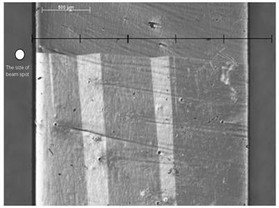
Figure 1. Highly mobile twin interface and associated domains in Ni-Mn-Ga single crystal observed using interference contrast (Nomarski contrast) with a Zeiss microscope. The XRD scans were performed horizontally along the macroscopic twin boundary. The size of the X-ray beam spot is marked on the left. Width of the sample is about 2.3 mm.
Experimental
The X-ray diffraction measurements were performed using X’Pert PRO PANalytical θ-θ horizontal powder diffractometer. The Co anode (λ = 1.78901) with point focus was used as an X-ray source. The irradiated volume was defined by a monocapillary with inner radius 0.1 mm, the approximate beam size is shown on the left-hand side of Fig. 1. This small beam makes possible a relatively precise x-direction mapping along the boundary. The sample was attached to ATC-3 texture cradle enabling rotation, inclination (ψ) and x-movement of the sample. Simultaneous movement of the tube and detector allows for precise change of incident angle (ω). The diffracted beam was either limited by Soller slits (0.02 rad) to confine the ψ-range of diffracting planes (up to ≈ 1°) or the slit were removed to allow simultaneous detection of two diffraction lines whose positions differs by as much as ≈ 3°. The X’Celerator multiple strip detector was used to detect the diffracted beam.
Firstly the sample is preoriented towards the laboratory system. Several
ω-scans are performed for various angles ψ until the values of ψ
and ω of any strong reflection
are found. At the beginning the Soller slits are not used, when approximation
position of ψ is founded, then
the Soller slit can be inserted and the ψ-scan can be performed for
previously found ω.
Results and discusion
Relating to Fig. 1, the X-ray
diffraction confirmed that the upper part is c oriented and the lower part is a or b oriented perpendicularly to the plane. Since the
lattice parameters a
and b are very close, so their
corresponding diffraction are not well resolved. Fortunately high angle
diffraction (600) and (060) can be observed. Although these diffractions are very
weak (more than 100 times in comparison to (400)!), in the case of monocrystal
they have sufficient intensity to be detectable, see Fig. 2, and the
x-direction mapping is possible to be made, see Fig. 3.

Figure 2. Simultaneous
presence of á600ñ
and á060ñ
orientations in diffracting volume. These two diffractions are
relatively well separable. To avoid possible confusion, the spectral components
of wavelength distribution Kα1 and Kα2 are marked by vertical lines.
Figure 3. The x-direction mapping of ratios between a and b orientations. For two maxima in ω-scan also two
2θ-scans were done for each position x.
The x-direction mapping shows that
in diffraction volume limited by monocapilary (~ 0.12
x 0.14 x 0.01 mm) occurs both a and b oriented
variants. And that the period of possible a-b twinning is under spatial
resolution of laboratory experimental conditions.
References
1. L. Straka – thesiss, http://lib.tkk.fi/Diss/2007/isbn9789512288205/
2. N. Lanska, , , , , , J. Appl.Phys. 95, 8074 (2004)
3.
L. Straka, N. Lanska, K. Ullakko,
A. Sozinov, Appl. Phys. Lett., 96, (2010), 131903
Acknowledgements.
The financial supports by the Czech Science Foundation
via grant
No. P107/11/0391 and
the