Electron
diffraction – SAED, CBED, PED
M. Klementová
Institute
of Inorganic Chemistry of the ASCR, v.v.i., 250 68 Husinec-Řež 1001, Czech
Republic
klemari@iic.cas.cz
Keywords: electron diffraction, SAED, CBED,
PED
Introduction
Due to a much
stronger interaction of electrons with matter compared to X-rays, electron
diffraction has non-negligible advantages over X-ray diffraction. Nano-objects
that are too small for conventional X-ray diffraction experiment and would have
to be taken to a synchrotron can be studied in the laboratory by electron
diffraction. Electron diffraction is readily available on any TEM (transmission
electron microscope) where it can be further combined with other complementary
techniques such as imaging and/or spectroscopy. Moreover, electrons are
scattered by light atoms relatively more strongly, and electron diffraction
patterns can show reflections corresponding to a resolution beyond that
available with X-rays. However, the much stronger interaction of electrons with
matter as well as very small diffraction angles also cause strong dynamical
diffraction effects, such as multiple diffraction, which hinder structural
interpretation of electron diffraction patterns.
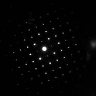
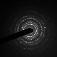
SAED –
Selected-area electron diffraction
In SAED [1],
a parallel beam (plane wave travelling in one direction) interacts with sample.
An aperture is used to define the area from which the diffraction pattern is to
be recorded from a thin sample. This aperture is typically located in the first
image plane below the sample. Typical size of an area studied by SAED is a few
hundred of nanometers. SAED diffraction patterns are either simple spot patterns
corresponding to single-crystal diffraction or ring patterns corresponding to
powder diffraction from multiple crystals with a variable orientation (Fig. 1).
SAED is
commonly used for phase identification, determination of structural intergrowth,
determination of growth directions etc. Lattice parameters from SAED
have accuracy of approx. 5%, and due to multiple diffraction
kinematically forbidden reflections are often present.
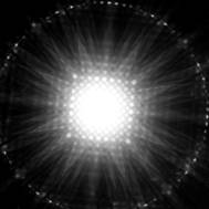
CBED –
Convergent-beam electron diffraction
In CBED [2],
the incident electron beam is a cone of incident rays impinging on sample over
a range of angles. As a result, a diffraction spot will appear as a disc in the
back focal plane (Fig. 2). Such disc contains information from higher-order
Laue zones (HOLZ). Using convergent beam overcomes the limitation of SAED for
analyzing only areas of approx. 500 nm in size. However, with CBED, the areas
studied are limited by the beam size and the beam interaction volume (approx.
10 nm).
CBED yields
information about specimen thickness, unit-cell parameters (accuracy of approx.
0.01%), crystal system and 3D crystal symmetry (point group and space group).
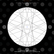
PED –
Precession electron diffraction
PED is
equivalent to the Buerger precession technique [3] used in X-ray diffraction
where the specimen as well as the photographic plate circumscribe the surface
of a cone (the precession movement) with
respect to the X-ray incident beam in order to record an undistorted image of
reciprocal space. In the electron precession technique, it is the electron beam
that is tilted and moved along the cone surface having a common axis with the
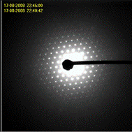
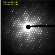
TEM optical axis and with the studied zone axis of the specimen (Fig. 3).
PED was
first proposed by Vincent & Midgley [4]. The data show reduced dynamical
effects because there are far fewer simultaneously excited reflections in the
off-zone condition. In addition, the precession integrates the diffraction
intensities through the Bragg condition, which provides data sets less subject
to minor sample tilt, and makes the interpretations of pattern symmetry more
reliable.
|
a) |
b) |
|
Figure 1. SAED: a) spot pattern – SnO2
along [001], b) ring pattern – RuO2. |
|
|
a) |
b) |
|
Figure 2. CBED: a) including HOLZ – SnO2
along [001], b) simulation of centre disc of CBED by JEMS – SnO2 along
[100] [5]. |
|
|
a) |
b) |
|
Figure 3. Electron diffraction of mayenite:
a) precession off, b) precession on [6]. |
|
References
2. J.B.
Poole, Philiops Tech. Runsch., 9,
33.
1. W. Kossel,
G. Möllenstadt, Ann. der Phys., 36, (1939), 133.
3. M.J. Buerger, The precession method in X-ray crystallography. John Wiley and Sons, Inc. New York. 1964.
4. R. Vincent, P.A. Midgley, Ultramicroscopy, 53, (1994), 271.
5. P. Stadelmann (2009). JEMS—ems java
version, CIME-EPFL,CH-1015 Lausanne, Pierre.Stadelmann@epfl.ch.
6. http://www.nanomegas.com/liveNew.php - downloaded on June 1, 2009.
Acknowledgements.
Financial support through project AV0Z40320502 is gratefully acknowledged.