Surface
layers study of bulky samples by X’Pert PRO diffractometer
Z.
Pala1,
1Department
of
2Institute
of Physics of the ASCR, v. v. i., Na Slovance 2, 182 21
zdenek.pala@fjfi.cvut.cz
Samples for
investigation by means of X-ray diffraction are frequently prepared solely and,
therefore, suitably for the experimental arrangement, which often imposes
stringent conditions to its shape, mass and dimensions. However, real samples
from industrial production cannot be usually cut into feasible parts without
changing their structural and physical properties. Generally, samples’ amendments
can even lead to redistribution of residual stresses by inducing new plastic
deformations. Consecutive inspection of such artificially created objects has
only limited relevance to the original state which is the centre of interest.
The appropriate
attitude to XRD measurements of bulky and heavy samples is, first of all, a
choice of convenient goniometer geometry. The theta-theta goniometer
configuration offers comparatively large space for sample handling. Preferably,
the sample mounting should be external and, thus, allowing placement of large
volume beneath the investigated surface. Such external mounting stages should
have large travel range with smallest possible position resolution and reading
accuracy in both vertical and horizontal directions. Consequently, sufficiently
precise position control cannot be omitted. This can be done by a high
precision laser sensor for dimensional measurement which has ample resolution
up to
In the experiment,
three types of machined surface layers for guide gibs of dimensions 160×105×45
mm3 were examined. Samples from the steel 11 375.0 were machined by
milling, grinding, and scraping. Semiproducts were cut from the steel sheet
without any heat treatment by using an acetylene jig-burner. The aim of the
research was to characterize each surface by state of macroscopic residual
stress on the very surface and in near surface area of ca 200 μm in depth.
Moreover, profiles of diffraction line {211} of α-Fe phase were used for
calculation of microstrains and domains of coherent scattering by the single
line Voigt function method [1]. Microhardness and metallographic measurements
provide a supplement to diffraction results.
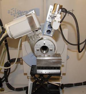
Figure 1. Mounting of a guide guib for
residual stress measurement by X’Pert PRO.
Sample positioning
in the X’Pert PRO diffractometer is depicted in Fig.
State of biaxial macroscopic
residual stress (RS) on the surface was established on three chosen areas of
each sample in order to find out, in the first approximation, level of RS
homogeneity in final surface. RS depth distribution was obtained by successive
layer removal by electro-chemical polishing. Sets of diffraction data were
evaluated by centre of gravity algorithm and biaxial state was assumed, shear
stress was recorded only in ground surface. Results of RS after layer removal
were corrected according to Moore and Ewans method [4].
Figure 2a. Residual stress distribution in
milled surface.
Figure 2b. Residual stress distribution in
ground surface.
Figure 2c. Residual stress distribution in
scraped surface.
References
1. Th.H. de Keijser, J.I. Langford,
E.J. Mittemeijer, A.B.P. Vogels J. Appl. Cryst., 15, (1982), 308.
2. www.standa.lt
3. X’Pert PRO User’s Guide, Fourth
Edition, 2002.
4. Sikarskie D., Trans. of the
Metallurgical Society of AIME. 239 (1967) 577 – 580.
Acknowledgements.
The
research was supported by the Project MSM № 6840770021 and by the Project
№ FT-TA4/105 of the Ministry of Industry and Trade of the