Texture and
stress measurement with the Eulerian cradle on MRD system, double-mirror setup
R. Kužel
Department of Condensed Matter
Physics, Faculty of Mathematics and Physics,
Measurement with
Eulerian cradle
For complete texture and stress analysis, it is necessary to measure reflections not only from the lattice planes parallel to the surface as in Bragg-Brentano symmetrical q-2q scans or at specific inclinations like e.g. for parallel beam 2q scans. Instead, information from large scale of inclinations is necessary. Either their diffraction peak intensities (for texture) or positions (for stress) are required. Traditionally Eulerian cradles are use for this purpose in combination with point focus of the tube and collimators. However, big disadvantage of this arrangement is significant defocusation and also loss of intensity. Therefore in modern diffractometers polycapillaries are used behind the X-ray tube which produce transforms divergent beams into a beam parallel in all directions. There is still some divergence there but the suppression of defocusing effects and gain in intensity is significant. The arrangement can be in principle seen on Fig. 1 which differs only in one element, the Goebel mirror should replaced by polycapillary module for texture and stress measurement (of course, also the tube should be rotated by 90 ° in order to use point focus).
Figure 1. Photo of MRD Pro system with Eulerian cradle.
Not only full texture measurement but also fast ψ or φ scans can easily be done with the cradle.
Two software packages are available from Panalytical – X’Pert Texture and X’Pert Stress.
Texture software provide basic functions for display of pole figures in several views (Figure 2) and calculation of ODF – Orientation Distribution Function. Unfortunately, there not many options for example for precise scaling of the plots and their export. Nevertheless, basic needs of texture characterization are met.
Figure 2. Pole figure (111) of 1 pass ECAP deformed Cu sample in classical contour plot (left) and the so-called 2.5 D plot (right).
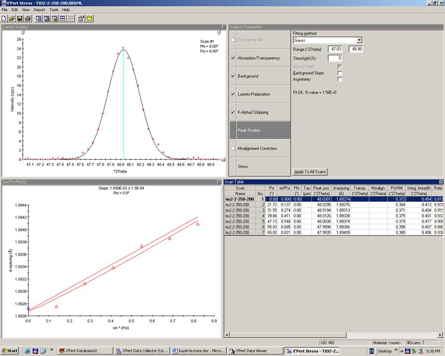
Figure
3. Basic screen of X’Pert Stress. Peak positions are
determined automatically for all measured lines but the position of each
individual peak of sin2ψ plot (left bottom) can be determined
by different algorithm (center of gravity, parabola, Gauss, Lorentz, Pearson,
pseudo-Voigt function, manually). The following corrections can be applied –
absorption, transparency, Lorentz-polarization, misalignment, Ka2 stripping.
On the other hand, stress software is very user-friendly. It allows both automatic and manual data processing and very fast and flexible stress evaluation not only in approximation of uniaxial stress (nonlinearity in sin2ψ plot, triaxial stress). Database of elastic constants for some materials can be used and modified by the user.
Double-mirror setup
Nowadays, the measurement using parallel beam and Goebel mirror is more or less routine especially for thin films, when 2q scans with small angles of incidence are required. This arrangement gives quite high intensity but rather poor resolution that is 3-4 times worse than for conventional Bragg-Brentano focusing geometry. In case of nanocrystalline films this is not that big problem because physical broadening is significantly higher. However, for films with better crystallinity and not so high strains, the physical broadening is close to the instrumental one. In this case, the insertion of the second mirror in the diffracted beam can help. It converts the parallel beam to convergent one and resulting resolution is back close to the one of B-B setup. Picture of the setup on X´Pert Pro vertical system is on Fig. 4.
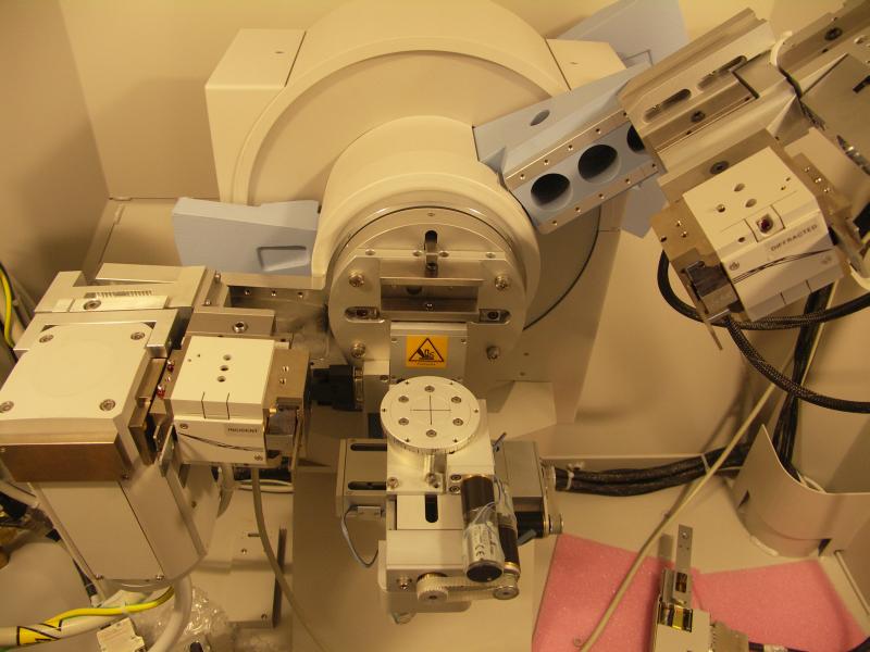
Figure 4. Double-mirror setup on vertical diffractometer.
When to use this setup? In all cases, when high resolution and parallel beam on the sample are required simultaneously
· Thin film studies with low angles of incidence. In this case, there is one significant disadvantage – the acceptance of the second mirror is very limited (to about 1.5 mm) so that the useful sample area is limited by this dimension. It lead to intensity drop and may cause difficulties for samples with large grains
· When precise specimen positioning in the goniometer axis is difficult – irregularly shaped surface, rough surface, usage of different chambers. In such cases, even symmetrical q - 2q scans may be of interest. They give not much lower intensities than focusing BB setup with similar resolution. It is well known that focusing geometries are very sensitive to careful alignment. Double-mirror setup can overcome this drawback.