Keywords
nanoindentation,
NanoTestTM, thin films
Abstract
The depth
sensing indentation technique is increasingly being used to probe the mechanical
properties of materials. There is referenced the Oliver-Pharr method for
analyzing indentation load-depth data in this paper. We determined the hardness
and the elastic modulus of thin films prepared by magnetron sputtering
experimentally using The NanoTestTM instrument. Load was applied by
force in horizontal direction. This untraditional arrangement of the experiment
allows just original construction of the NanoTest platform.
1. Introduction
The chemical
resistant and the high hardness of diamond-like carbon films allow some tribology
applications. Amorphous carbon films commonly have resistance against abrasive
and adhesive wear and the low coefficient of friction. Special thin films can
enlarge the operating lifetime of product. Research and development of new and
superior procedures of the surface treatment of material can bring significant
increase of product manufacture qualities moreover savings of the critical
materials. An Investigation of mechanical properties allows produce layers and
coatings with exactly defined features.
The Instrumented
indentation offers advances in sensitivity and data acquisition. These benefits
are significant in materials science particularly regarding fundamental
mechanisms of mechanical behaviour at micrometer and even sub-micrometer length
scales.
We examined a-C
a a-C:Si films from amorphous carbon on Si substrates. The thin films produced
by the DC magnetron sputtering from carbon target in chemically poor argon in
vacuum chamber (with the stuck Si little sheet in the second case) of
commercial vacuum machinery the Leybold Z 550M. A description of the
sputtering equipment and deposition parameters were published previously e.g. [1].
Thickness of the layers was measured by the ALPHA STEP 500 apparatus. Sample a-C
no. 516: 1,62 mm, sample a-C:Si no. 846-1: 2,29 mm. We measured certain silicon films as well. Its
indentation behaviour is more complicated by cracking and pressure-induced
phase transformation [2, 3].
2. Instrumented
indentation
Depth sensing indentation
(DSI) also known as instrumented indentation or nanoindentation [4] is
increasing being used to evaluate the mechanical properties of materials having
very fine microstructure such as thin films. In contrast to traditional
hardness testers instrumented indentation systems allow the application of a
specified force or displacement course. The force and the displacement are
controlled and measured simultaneously and continuously over a complete loading
cycle. Moreover the extremely small force and displacement resolutions often <
1 mm are possible.
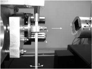
Fig.
1.
Indentation part of the NanoTestTM
system: 1 – indenter, 2 – samples, 3 – pendulum, 4 – capacitor plates, 5 –
sample holder with x-y-z nano-feedings, 6 – microscope.
Many
instrumented indentation systems can be found on the market. We used commercial
the NanoTestTM NT600 platform. The instrument makes use of its
unique pendulum design (Fig. 1). The pendulum pivoted on
frictionless bearings combines vibrating stability with the ability to carry out
a wide range of measurements. To measure nano-mechanical properties a very
small calibrated diamond indenter is brought into contact with the sample
surface and a load is applied by means of a coil and magnet located at the top
of the pendulum. The resultant displacement of the probe into the surface is
monitored with a sensitive capacitive transducer in real time as a function
of load [5].
After reaching
a predefined maximum value the load is reduced and the penetration depth
decreases due to the elastic recovery of the deformed material. The depth and
load are monitored continuously which allows both hardness and elastic modulus
to be determined.
3. Analysis of
the nanoindentation data
Different
analytical approaches were developed to extract mechanical properties,
generally the hardness H and the
elastic modulus E. The Oliver-Pharr
method introduced in 1992 [6] and refined in 2004 [7] comes from former publications
such as [8]. This principle is used in the characterization of mechanical behavior
of materials at small scales. By this techniques a mechanical properties can be
determined directly from indentation load and displacement measurements without
the need to image the hardness impress. For this reason, the method has become
a primary technique for determining the nano-mechanical properties of thin
films and small structural features.
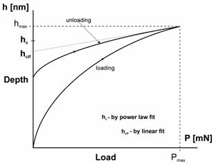
Fig. 2. One cycle of load-displacement data and contact
depth determination.
In principle the method was developed to
measure the hardness and elastic modulus of material from indentation
load-displacement data obtained during one cycle of loading and unloading
(Fig. 2). Parameter
P is the load and h the displacement relative to the
initial non-deformed surface. The
method is essentially an extension of the method proposed by Doerner and Nix [8]
(linear fitting – Fig. 2). Experiments have shown that unloading curves
are distinctly curved and P-h
raw data are usually well approximated by the power law
relation (1). Where a , hf and m are
constants.
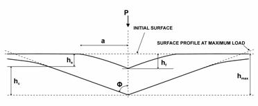
Fig. 3. Schematic illustration of the unloading
process [6, 7].
There are three
important quantities that must be measured from the curves. The maximum load Pmax, the maximum
displacement hmax and S the elastic unloading stiffness [7] (contact
stiffness [9]) defined (3) as the slope of the upper portion of the
unloading curve during the initial stages of unloading. Another important quantity
is the final depth hf the
permanent depth of penetration after the indenter is fully unloaded. The
accuracy of hardness and modulus measurement depends on how well these
parameters can be measured experimentally.
There are a
cross section of an indentation and the analysis parameters in Fig. 3. Total
displacement is written as (2). Distance hs
is the displacement of the surface at the contact perimeter.
The contact
depth hc (likewise called
plastic depth [8]) is the depth of indenter in contact with the
sample under maximal load (4). The geometric constant for the Berkovich
indenter e = 0,75. This value comes
from modelling [6] by a paraboloid geometry.
The area of
contact is determined by the geometry of the indenter and the depth of contact
by area function (5) which relates the cross-sectional area of the
indenter to the distance from its tip. This function must be established
experimentally prior to analysis. For a perfect Berkovich indenter the Ac = 24,5·hc2. A real
indenter is never perfect due to some tip rounding. The function may be determined
for an example as (6) type where L
and K are constants.
Measurements of
the initial unloading slope can be used to determine the reduced modulus Er. The reduced modulus is
related to the contact area and measured stiffness by (7).
The equation (8) takes
account effects of non-rigid indenters on the load-displacement behaviour. Ei and ni are
Young´s modulus and Poisson´s ratio for the indenter (diamond) which can be
taken as 1 141 GPa and 0,07 respectively [5], E and n are properties of the sample.
The data
obtained using the Oliver-Pharr method can be used to determine the indentation
hardness defined by equation (9).
4. Experiment
We measured
both carbon samples stuck on the one dural sample holder by quick drying cyanoacrylate
industrial superglue Permabond. The silicon films we affixed by a wax on another
dural holder. The melting temperature of the wax is approximately 60°C.
The experiment
we programmed in the control NanoTest software. The indents we arranged to a matrix
(Fig. 4). The matrix consisted from several single indents in one column
measured at one maximum load with the indentation offset 30 mm. The dimension of the matrix in horizontal
axis is given by number of experiments at one maximum load. There is possible
up to 100 indentation experiments each containing up to 100 indentations to be
scheduled in the NanoTest control software [5].
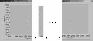
Fig. 4. The matrix of indents defined in the NanoTest
software.
The experiment was controlled by electronic control unit and the computer. Before the auto-run we left the instrument and prepared samples at the constant temperature 26°C during 6 hours.
5. Results
Determined dependencies
of hardness and reduced elastic modulus versus maximum load on measured carbon
films are in the following figures. Some measurement results on silicon film
are shown too.
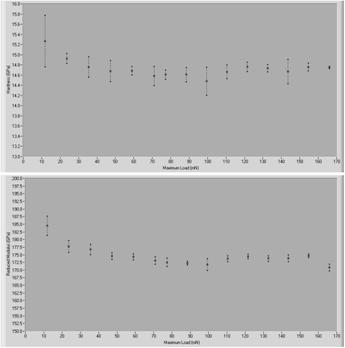
Fig. 5. Hardness and reduced modulus vs. maximum load
on carbon film (sample no. 516).
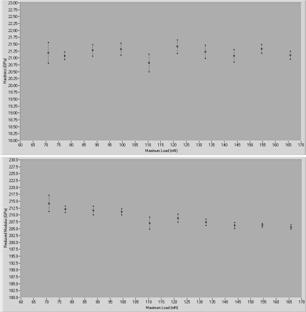
Fig. 6. Hardness and reduced modulus vs. maximum load
on carbon film (sample no. 846-1).
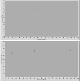
Fig. 7. Hardness and reduced modulus vs. maximum load
on silicon film (sample no. 941).
Acknowledgements
This work was supported by Institutional Research Plan No. AV0Z10100522.
References
1. V. Kulikovsky, P. Bohac, F. Franc, A. Deineka,
V. Vorlicek, L. Jastrabik, Hardness, intrinsic stress, and structure of the a-C
and a-C:H films prepared by magnetron sputtering. Diamond and Related Materials, 10 (2001) 1076–1081.
2. G.M. Pharr, W.C. Oliver & D.R. Clarke,
Hysteresis and discontinuity in the indentation load-displacement behavior of
silicon. Scripta Metallurgica, 23 (1989)
1949–1952.
3. G.M. Pharr, W.C. Oliver & D.S. Harding, New
evidence for a pressure-induced phase transformation during the indentation of
silicon. Journal of Materials Research,
6 (1991) 1129–1130.
4. M.R. VanLandingham, Review of Instrumented
Indentation. Journal of Research of the
National Institute of Standards and Technology, 108 (2003) 249–265.
5. B. Beake, S. Goodes et al : Micro Materials
NanoTest User Manual Version 2.0. Wrexham 2003. Micro Materials Ltd.
6. W.C. Oliver, G.M. Pharr, An improved
technique for determining hardness and elastic modulus using load and
displacement sensing indentation experiments. Journal of Materials Research, 7 (1992) 1564–1583.
7. W.C. Oliver, G.M. Pharr, Measurement of
hardness and elastic modulus by instrumented indentation: Advances in
understanding and refinements to methodology. Journal of Materials Research, 19 (2004) 3–20.
8. M.F. Doerner, W.D. Nix, A method for
interpreting the data from depth-sensing indentation instruments. Journal of Materials Research, 1 (1986)
601–609.
9. J. Gong, H. Miao & H. Peng, Analysis of
the nanoindentation data measured with a Berkovich indenter for brittle
materials: effect of the residual contact stress. Acta Materialia, 52 (2004) 785–793.