X-ray Diffuse
Scattering from Dislocation loops in Czochralski Grown Silicon Wafers
P. Klang*[1], V. Holý1,2
1 Institute of Condensed Matter
Physics, Masaryk University, Brno, Czech Republic
2 Faculty of Mathematics and Physics,
Charles University, Prague, Czech Republic
Defects in
silicon wafers are used for gettering metal impurities during the device
processing. We have studied Czochralski grown silicon wafers (001) using
triple-axis high-resolution X-ray diffraction (see measured reciprocal space intensity
distribution map in Fig. 1). These wafers from different positions of the ingot
were annealed at high (1050°C / 16h) or low and high temperature
(750°C / 4h + 1050°C / 16h). In this work we have specialized in samples with intensity
streaks perpendicular to {111} planes in measured reciprocal space maps.
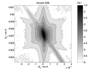
Figure 1. Measured symmetrical (004)
diffraction reciprocal space map of annealed (750°C / 4h + 1050°C / 16h)
silicon wafer.
We will discuss
deformation field and X-ray diffuse scattering from dislocation loops
(including stacking faults) in silicon crystal. The reciprocal space intensity
distributions were modelled using the Krivoglaz theory [1]. The exact
equation for deformation field from dislocation loops from Burgers theory of
elasticity is used to computation the deformation field. These results have
been compared with the approximate asymptotic equations from Larson, Schmatz
[2] (see Fig. 2).
The dislocation
loops are placed in four equivalent planes {111}. Four streaks in the perpendicular
directions <111> should be observed in the measured data, however due to
the symmetry and the orientation of the sample, two streaks coalesce in one
together with truncation rod. We used three most common types of dislocation
loops in {111} planes in silicon: stacking faults with burgers vectors b = a/3<111>, perfect dislocations
with b = a/2<110>
and Shockley dislocation with b = a/6<112>. The final reciprocal space intensity distribution
is sum over combinations of equivalent planes and burgers vectors (four for
stacking faults, 24 for others). These simulations for the loop with radius
0,7μm are in Fig. 3.
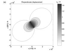
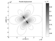
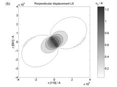
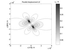
Figure 2. Size of simulated displacement field
from stacking fault in (111) plane with b = a/3[111] (in parallel and
perpendicular direction to stacking fault) using (a) Burgers and (b) Larson
theory.
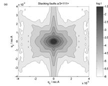
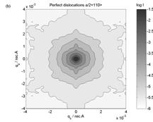
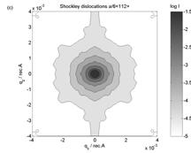
Figure 3. Simulated reciprocal space intensity
maps from (a) stacking faults, (b) perfect dislocations and (c) Shockley
dislocations with radius 7000A.
The symmetry of
measured reciprocal space map determines the type of dislocation loops and from
FWHM of the intensity streak we can obtain the radius of the loops. Good
agreement of the theory with the experimental data was achieved for the model
of stacking faults.
[1] M. A.
Krivoglaz, Diffraction of X-rays and Neutron in Nonideal Crystals, Springer,
Berlin 1996
[2] B. C.
Larson and W. Schmatz, Phys. stat. sol
(b) 99 (1980) 267