Probing Non‑trivial Layer-Substrate Orientational Relationships Using Wide Reciprocal Space Mapping
Lukáš Horák1, Radomír Kužel1, Milan Dopita1, Josef Buršík2
1Charles University, Faculty of Mathematics and Physics, Prague, Czech Republic
2Institute of Inorganic Chemistry of the Czech Academy of Sciences, v.v.i., 250 68 Husinec-Řež 1001, Czech Republic
lukas.horak@matfyz.cuni.cz
Introduction
Strongly oriented polycrystalline thin films and epitaxial layers typically exhibit a well-defined crystallographic relationship with their substrates. Describing and understanding this relationship is essential for interpreting the structural, electronic, and functional properties of thin-film systems.
For epitaxial layers, the orientation relationship is most commonly investigated using high‑resolution reciprocal space mapping (HR‑RSM), which relies on a limited set of predicted unit‑cell orientations derived from lattice matching considerations. In this case, the experiment primarily serves to verify one of the anticipated configurations. In contrast, strongly textured polycrystalline films are usually characterized by pole‑figure measurements, which probe all crystallographic orientations present in the film. This approach, however, requires reasonably well-known lattice parameters in order to select appropriate diffraction conditions, which are not always available.
In some systems, the film texture or epitaxial relationship is neither obvious nor intuitive. In such non‑trivial cases, no diffraction peaks from the layer appear at the expected positions, and no layer reflections are observed in symmetric θ-2θ scans, indicating the absence of any low‑index crystallographic plane parallel to the surface. Pole‑figure analysis may also become impractical when lattice parameters are uncertain or when the number of diffracted peaks is large and overlaps significantly with substrate reflections, making reliable interpretation extremely difficult.
We define non‑trivial layer-substrate orientation relationships as configurations in which the layer is both in‑plane and out‑of‑plane oriented, yet no low‑Miller‑index plane of the layer is parallel to the substrate surface (or to a near‑surface crystallographic plane of the substrate), and where only a minimal number of planes or directions are aligned in an unintuitive manner relative to the substrate lattice.
In such situations, conventional techniques-high‑resolution reciprocal space mapping, symmetric θ-2θ scans, and pole‑figure measurements are either insufficient or require laborious experimental effort. We therefore propose the use of low‑resolution wide reciprocal space mapping as a fast, robust, and largely foolproof experimental approach. This method rapidly collects comprehensive reciprocal‑space information, limited primarily by instrumental resolution, without requiring prior assumptions about lattice parameters or orientation relationships.
In the following sections, we briefly describe the wide reciprocal space mapping methodology and present results from one representative systems: strongly textured polycrystalline M‑type hexaferrite thin film grown on R‑cut sapphire (ALO) substrate. Previous studies have shown that M‑type hexaferrites grown on Al₂O₃ or MgO substrates exhibit substrate‑dependent crystallographic orientations, with well‑defined low‑index alignments on C‑cut sapphire and MgO(111), but increasingly complex and tilted configurations on A‑, M‑, and especially R‑cut sapphire [1-4]. However, across all these substrate cuts, the approximate crystallographic relationship appears to be universal. Thus, even though there existed well‑justified expectations for the layer orientation based on crystallographic considerations, we demonstrate that the actual growth results in non‑trivial orientation relationships, with no low‑index planes parallel to the substrate surface, arising from a small tilt of the substrate lattice along a specific in‑plane direction.
Methods
The crystallographic orientation relationships between the thin films and their substrates were investigated using wide reciprocal space mapping (WRSM), a low‑resolution X‑ray diffraction technique currently being developed in our laboratory. WRSM is designed to rapidly probe a large volume of reciprocal space without requiring any prior knowledge of lattice parameters, expected texture components, or preferred orientations. The method serves as a complementary approach to conventional pole‑figure measurements and powder diffraction, enabling simultaneous phase identification and texture analysis in strongly oriented thin films.
WRSM measurements were performed using a laboratory X‑ray diffractometer equipped with a rotating Cu anode source. The primary X‑ray beam was vertically parallelized using a parabolic mirror and further defined by a vertical slit limited to 0.5 mm. Horizontal collimation was achieved using two sequential slits, each with a width of 0.5 mm. The diffracted intensity was collected using an area detector with an active area of 38.5 × 77.5 mm² (vertical × horizontal) and a pixel size of 0.1 × 0.1 mm². The detector was positioned at a distance of approximately 15 cm from the sample and operated without secondary optics, allowing the collection of a broad angular range of diffracted signals. Both the X‑ray source and detector arms moved in the vertical diffraction plane.
Reciprocal space maps were acquired in symmetric skew geometry using extended θ-2θ scans. In this configuration, each θ-2θ scan corresponds to a straight radial trajectory in reciprocal space. By tilting the sample by an angle χ, this trajectory becomes tilted accordingly within reciprocal space, enabling access to a wide range of orientations. During each θ-2θ scan, the diffracted intensity collected by the area detector was projected onto a two‑dimensional stripe, effectively reducing the dimensionality of the data.
To reconstruct planar cuts of reciprocal space, θ-2θ scans were repeated for a sequence of sample tilt angles χ. The tilt step was chosen to ensure minimal overlap between adjacent stripes based on the solid angle covered by the detector; in our setup, an optimal χ step of 15° was used. Individual stripes obtained at different tilt angles were combined to form a two‑dimensional reciprocal space map corresponding to a single sample azimuth.
To assess in‑plane orientation, the planar reciprocal space reconstruction was repeated for multiple sample azimuthal rotations φ. An azimuthal step of 15° was sufficient to capture symmetry‑related features for common substrate orientations, while smaller steps could be employed when smoother intensity reconstruction was required. The complete dataset thus provided a series of reciprocal‑space sections containing the out‑of‑plane direction Qz , collectively enabling qualitative and quantitative assessment of both out‑of‑plane and in‑plane texture.
Experimental WRSM data were analyzed by direct comparison with numerical simulations of reciprocal‑space intensity distributions for the substrate and possible film phases. Simulations included contributions from single‑crystalline substrate reflections, textured film components, and randomly oriented crystallites, which manifest as Debye-Scherrer rings. Sharp and intense diffraction spots were associated with dominant texture components, while continuous rings indicated polycrystalline fractions.
The texture models were iteratively adjusted until good agreement between experimental maps and simulations was achieved, yielding angular resolution of the determined orientations on the order of 1°. This approach enabled reliable determination of complex and non‑trivial layer-substrate orientation relationships that could not be resolved using conventional θ-2θ scans, high‑resolution reciprocal space mapping, or pole‑figure analysis.
Results
The crystallographic texture and orientation relationship of M‑type hexaferrite films grown on R‑cut sapphire substrates were primarily investigated using wide reciprocal space mapping (wRSM). The blindly collected full 3D diffraction data shown in Figure 1 allowed determining the phase and the texture. In contrast, conventional symmetric θ-2θ scans did not reveal any intense film diffraction peaks for this system, indicating only the absence of any low‑index hexaferrite plane parallel to the substrate surface.
Representative wide reciprocal space map for the M‑seed and M‑bulk hexaferrite layers deposited on Al₂O₃ (R‑cut) substrates are shown in Fig. 3. The experimentally measured diffracted intensity distributions (grey scale) were successfully reproduced by numerical simulations including contributions from the sapphire substrate, the hexaferrite layer, and a minor hematite phase. The agreement confirms that wRSM provides reliable access to the full three‑dimensional reciprocal‑space information in the presence of complex textures.
|
|
|
|
Figure 1. Top view of the diffracted intensity distribution in three‑dimensional reciprocal space acquired by wide reciprocal space mapping (wRSM). The out‑of‑plane reciprocal‑space coordinate Qz is encoded by the color scale. Each wide RSM represents a vertical reciprocal‑space section containing the Qz axis. By repeating the mapping for different azimuthal angles with a fine azimuthal step, the complete three‑dimensional reciprocal space can be reconstructed. |
Figure 2. Representative wRSM (vertical cut through reciprocal space). Experimental data (grey scale) are overlaid with numerical simulations for the Al2O3 substrate (cyan spots), the M-type layer (red), and a minor hematite phase (yellow). Concentric Debye rings indicate the presence of randomly oriented crystallites within the film, whereas sharp, intense diffraction spots correspond to the dominant texture component. |
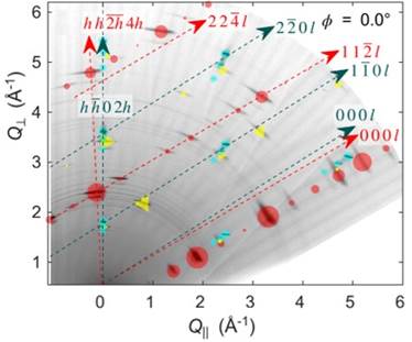
In the reconstructed reciprocal‑space sections, diffraction‑spot chains corresponding to the sapphire substrate (h-h 0 l) and the hexaferrite layer (hh-2h l) are clearly visible. The directions of these chains directly reflect the orientations of the crystallographic c‑axes of the substrate and the layer. From their relative inclination, a mutual misalignment of approximately 2° between the substrate and layer c‑axes was determined. This misorientation is not observable in conventional θ-2θ geometry but is unambiguously resolved in wRSM.
Importantly, the tilt between the nominally corresponding planes (1-102) ALO and (11-24)M is directly accessible in a reciprocal‑space section chosen perpendicular to the in‑plane directions [11-20]ALO∥[1-100]M, which were identified as exactly parallel from the complete wRSM dataset. The observed angular separation between the respective diffraction‑spot chains corresponds to the true out‑of‑plane tilt of the hexaferrite lattice with respect to the substrate.
Analysis of maps recorded at different sample azimuths demonstrates that this tilt is azimuthally dependent and follows a well‑defined in‑plane crystallographic direction of the substrate. Magnified regions around selected layer and substrate reflections (see Figure 3) further reveal that the tilt distribution is relatively broad, with an angular spread on the order of several degrees, consistent with strong but non‑ideal texture.
Figure 3. X-ray diffraction wide reciprocal space maps for M-seed and M-bulk layers grown on a sapphire (R-cut) single crystal substrate. The experimental data in gray color scheme are overlayed by numerical calculations for the ALO substrate (cyan spots), M-bulk layer (red), M-seed layer (green), and minor phase of hematite (yellow). Pseudo-peaks produced by parasitic x-ray wavelengths are indicated by arrows. Panels (a-c) show magnified regions in the vicinity of the M-layer 1 1 -2 4 / Al2O3 2-204 diffraction spots for different sample azimuths. The displacement of the M-layer diffraction spots from the vertical dashed line corresponds to the projection of the tilt of the h h -2h 4h planes with respect to the sample surface (i.e., substrate planes h-h 0 2h), the elongation of the spots in angular direction indicate the width of the tilt distribution. Both the displacement and elongation is minimal for azimuth 90 deg. Panel (d) shows a magnified region near the M-layer 2 2 -4 0 / Al2O3 3 -3 0 0 diffraction spots, where the weak diffraction spot originating from the thin seed layer is clearly observable.
Pole‑figure measurements carried out for the hexaferrite 11-24 reflection qualitatively support the conclusions drawn from wRSM. The pole figure exhibits well‑defined intensity maxima distributed along a circle corresponding to a tilt angle of approximately 5° with respect to the surface normal. This result confirms that the hexaferrite layer is simultaneously oriented both in‑plane and out‑of‑plane, yet without any low‑index plane parallel to the substrate surface.
However, due to the high number of accessible reflections and partial overlap with sapphire peaks, the pole‑figure data alone are insufficient to uniquely determine the full orientation relationship. In contrast, wRSM directly provides the mutual alignment of crystallographic directions and planes without requiring prior assumptions about lattice parameters or expected texture components.
The combined wRSM and pole‑figure results demonstrate that, for R‑cut sapphire substrates, the hexaferrite layer adopts a non‑trivial layer-substrate orientation. Unlike growth on A‑, C‑, or M‑cut sapphire, the hexaferrite c‑axis does not align parallel to the substrate c‑axis, nor does the layer grow with any low‑Miller‑index plane strictly parallel to the substrate surface. These two requirements are geometrically incompatible in this system because of lattice‑parameter mismatch and differing axial ratios, leading to competing tendencies.
Instead, the system adopts a compromise configuration characterized by a distribution of tilts ranging from 0° to 6°, where all orientation possibilities shown in Figure4a-c are populated. This tilt is rotation of the hexaferrite lattice about a specific in‑plane axis ([-1 1 0 0] direction) that remains parallel to a corresponding substrate direction ALO [1 1 -2 0], see Figure 4d. On the other hand, this relationship od the inplane direction seems to be fixed with misorientation bellow sensitivity limit.
Figure 4. Visualization of the crystallographic relationship between the M-bulk layer and the substrate for different tilts of the M-phase (1 1 -2 4) planes: (a) zero tilt, with M-layer M-layer (1 1 -2 4) || ALO (1 -1 0 2); (b) intermediate tilt, where neither the surface planes nor the basal planes are parallel; and (c) large tilt, with M-layer (0 0 0 1) || ALO (0 0 0 1) . Owing to the different a/c lattice-parameter ratios of the layer and substrate, it is geometrically impossible for both the surface planes and the basal planes of the two unit-cells to be simultaneously parallel. In real sample, the tilt exhibits a broad distribution ranging from 0° to 6°. (d) Independent of the tilt shown above, the crystallographic directions M-layer [-1 1 0 0] and ALO [1 1 -2 0] remain parallel and form the common axis about which the tilt occurs.
Conclusion
We demonstrate that non‑trivial layer–substrate orientational relationships, in which neither low‑Miller‑index planes nor principal crystallographic axes are parallel to the substrate surface, can be reliably resolved using wide reciprocal space mapping (wRSM). Strongly textured M‑type hexaferrite thin films grown on R‑cut sapphire serve as a representative example.
The wRSM analysis reveals that the hexaferrite layer adopts a compromise orientation characterized by a small, well‑defined lattice tilt about a specific in‑plane direction that remains parallel to the substrate lattice. This configuration satisfies competing geometric constraints imposed by lattice mismatch and axial‑ratio differences between film and substrate, resulting in a non‑trivial orientational relationship that is neither obvious nor predictable from conventional epitaxial considerations. While pole‑figure measurements qualitatively confirm the presence and magnitude of the tilt, only wide reciprocal space mapping provides an unambiguous and comprehensive description of the full crystallographic relationship.
The method is particularly well suited for strongly textured or pseudo‑epitaxial thin films with complex, counter‑intuitive orientation relationships. As such, wRSM represents a powerful and broadly applicable tool for structural analysis of advanced thin‑film materials.
1. T. L. Hylton, M. A. Parker, K. R. Coffey, and J. K. Howard, J. Appl. Phys. 73, 6257-6259 (1993).
2. H. Liu, V. Avrutin, B. Xiao, E. Rowe, Ü. Özgür, and H. Morkoç, J. Cryst. Growth 312, 671-675 (2010).
3. S. A. Oliver, S. D. Yoon, I. Kozulin, M. L. Chen, and C. Vittoria, Appl. Phys. Lett. 76, 3612-3614 (2000).
4. P. C. Dorsey, T. D. B. Chrisey, J. S. Horwitz, P. Lubitz, and R. C. Y. Auyeung, IEEE Trans. Magn. 30, 4512-4517 (1994).
The work was supported by the project GA ČR, reg. No. 24-12710S