Effect of cold-rolling followed by shot peening on microstructural parameters in EN 1.4470 duplex steel
M. Rušin, J. Čapek, K. Trojan
Department of Solid State Engineering, Faculty of Nuclear Sciences and Physical Engineering, Czech Technical University in Prague
Duplex stainless steels (DSS) combine a microstructure of ferrite (α-Fe) with austenite (γ-Fe) in roughly 1:1 ratio. Chemical composition and content of alloying elements determine final properties, creating many types and grades of DSS. Most of DSS surpass austenitic stainless steels in their physical and chemical properties. Therefore, DSS are widely used in civil engineering, aviation and automotive industries, and even food storage. [1] Shot peening process (SP) is a cold working process known for its enhancement of service life by introducing compressive residual stresses into material. By bombarding the surface with small spherical media, plastic deformation is induced, altering real structure in subsurface regions. [2] Although rolling is nowadays a standard step in production and processing of steel products, its combination with SP introduces new possibilities for real structure modifications. Prior research of SP has shown that effects of rolling persist in the material and are not fully supressed even after SP. The effect of rolling was studied using X-ray diffraction techniques and the depth distributions of crystallite sizes and microstrains are described.
Three sheets of EN 1.4470 DSS with chemical composition (in wt.%): 22.2 Cr, 5.5 Ni, 3.28 Mo, 0.41 Si, 0.13 Cu, 0.09 Al, 0.034 V, 0.006 Nb, 0.005 Sn and bal. Fe, were cut and ground to different thicknesses. After stress relieve annealing, they were cold rolled to final thickness of 1.5 mm, achieving thickness reductions of 10, 40, and 50 % compared to original size after rolling. According to that, samples are designated as R10, R40 and R50 respectively. After another stress relieve annealing, the SP treatment was carried out in a self-made machine using quenched steel shots. Almen intensity 1.90 ± 0.08 mmA was achieved, measured by the arc height of A type Almen strip (strip thickness 1.295 ± 0.025 mm) [3]. The SP direction was the same as the rolling direction (RD). Due to limited penetration depth of X‑rays, layers of the material were gradually removed after each measurement, with aim to analyse the gradients of aforementioned parameters. PROTO Electrolytic polisher 8818‑V3 with A type electrolyte was used for electrolytic polishing. A micrometre screw gauge was used to determine the removed layer thickness by calculating the difference between thicknesses before and after polishing.
For obtaining the XRD patterns the Empyrean PANanalytical diffractometer in Bragg-Brentano geometry was used. Irradiated volume was defined by the experimental geometry, effective penetration depth of X-rays and the pinhole size (0.5 × 1 mm). Obtained patterns were used for Rietveld analysis using MStruct software. Crystallite sizes and microstrains were calculated from diffraction line broadening as described on the official website [4]. It has to be noted that γ-Fe is a metastable phase, and martensitic phase transformation is possible. Strain-induced martensite can by formed both by rolling and SP. In low carbon steels, the tetragonality of martensite lattice is small [3]. Therefore, these two phases cannot be directly distinguished by XRD techniques. Symbol α-Fe therefore represents both ferrite and martensite.
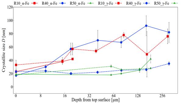
Results for crystallite sizes are shown in Fig. 1. As could be expected, SP process caused their reduction in near surface regions. The effect is however pronounced only to certain depth. Two effects of previous rolling can be seen, when comparing the samples to one another. Firstly, samples with lower thickness reduction have larger crystallites, due to lower deformation, both in bulk and near surface region. From this trend deviates only the α-Fe phase of R10 sample. After first two measured depths, sudden drop in its crystallite size was observed. This behaviour is related to the effect of preferred orientation in the material, which can alter the intensity of individual diffraction lines. Affected diffraction pattern is insufficient for an accurate determination of crystallite size. Inaccurate values were therefore omitted in Fig. 1. The explained trend in crystallite size due to different amount of rolling is rather expected. The second effect is of more interest. It can be seen in sample R50 and γ-Fe of sample R40, that the change in crystallite sizes between near surface regions, surely affected by SP, and bulk regions is less pronounced. This phenomenon can be attributed to work hardening. Samples rolled to higher thickness reductions are more deformed, therefore exhibiting harder surface. In contrast, surface of samples rolled to lower reduction is easily deformed by the impact of the SP medium. In DSS, the work-hardening rate of γ-Fe is higher than of α-Fe [5], explaining the difference between phases of R40 sample. However, the same effect in R50 sample was not observed for reasons that remain to be identified. From the overall results, it cannot be stated which phase of DSS was more affected. It should be emphasised again, that resulting values for α‑Fe are influenced by the crystallite size of the stress‑induced martensite. These crystallites originally correspond to γ‑Fe that underwent a phase transformation. However, the martensitic crystallites do not necessarily deform in the same manner as the α‑Fe crystallites.
|
|
|
Figure 1. The depth distributions of the crystallite size D. |
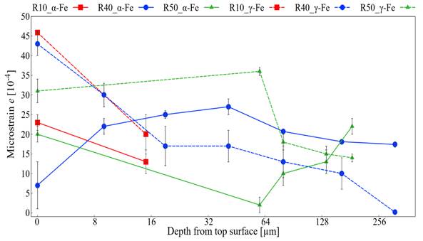
Microstrains were analysed together with crystallite sizes and are shown in Fig. 2. They are closely related to size of crystallites and can be seen as complementary results. Near surface regions are affected by SP, causing higher microstrains. Similarly to crystallite size, the change between surface and bulk region is less pronounced for higher reductions in γ-Fe phase. Results for α‑Fe are related to crystallite sizes. In larger crystallites, lower microstrains can be expected, which was also observed. For reasons described before, reliable results for R10 sample could not be obtained. Apart from this sample, the effect of rolling remains present in the samples despite their annealing. The reason is the mutual interaction between the crystallites of both phases during deformation. Both phases are deformed differently during rolling. For example, at small deformations, the work‑hardening rate of γ‑Fe is relatively high, however, once the thickness reduction exceeds 15%, the deformation becomes more concentrated in α‑Fe, which has higher stacking fault energy [5]. This might be the explanation behind sudden increase in microstrain of R50 α‑Fe phase in bulk region. The effect is not observed for R40 sample, due to its larger crystallites.
|
|
|
Figure 2. The depth distributions of the microstrain e×10–4. |
Generally, it was observed that rolling affects the further change of microstructural parameters caused by SP. Higher reduction in thickness introduces more strain hardening, which constrains further crystallite size reduction. With smaller crystallites, microstrain values tend to be higher. Unfortunately, R10 sample was highly affected by preferred orientation and to fully understand the effect of rolling on microstructural parameters, further research is needed.
1. TMR Stainless, Practical Guidelines for the Fabrication of Duplex Stainless Steel, London: IMOA, 2014.
2. J. Champaine, Shot Peening Overview, The Shot Peener, 2001.
3. M. Neslušan, P. Minárik, R. Čep, J. Uríček, K. Trojan, N. Ganev, L. Trško, Barkhausen noise emission of AISI 304 stainless steel originating from strain induced martensite by shot peening, Journal of Materials Research and Technology, 20, (2022), 748-762.
4. Z. Matej et al., “MStruct - software for MicroStructure analysis by powder diffraction” Online. Available at: https://www.xray.cz/mstruct/mstruct-basic-ex.html. [accessed 2026-04-16].
5. W. Reick, M. Pohl, A. F. Padhila, Determination of stacking fault energy of austenite in a duplex stainless steel, Materials technology, 6, (1996), 253-256.
This work was supported by the Grant Agency of the Czech Technical University in Prague, grant No. SGS25/168/OHK4/3T/14. We would also like to acknowledge prof. Dr. Ing. Miroslav Neslušan from University of Žilina for carrying out the SP process.