Neutron diffraction measurements of strain/stress state induced by a weld deposited pass
M. Vrána1,
P. Mikula1, Z. Nový2
1Nuclear Physics Institute
and Research Centre Řež, Ltd., 25068
Řež near Prague, Czech Republic.
2COMTES FHT, Borská 47, 320
13 Plzeň, Czech Republic
|
|
|
|
Fig. 1. Schematic diagram of elastic scattering of radiation defined by momentum vectors by a group of lattice planes (hkl). |
Fig. 2. Photo of two samples of steel plates of 15Ch2MFA with different weld deposited passes of Inconel 52. |
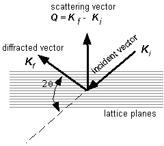

It is well known that in the case of components exposed to a thermomechanical load much attention is paid to investigations of strain/stress state of a basis material in the vicinity of welds where a nuclei of microcracks can arise. Neutron diffraction is a non-destructive method for determination of residual stresses in crystalline materials [1-3]. It can also be used for determination of applied stresses. The corresponding procedure can be employed within the interior of materials and adjacent to surfaces. In fact, neutron diffraction provides the values of elastic strain components parallel to the scattering vector which are then converted to stress. Neutron diffraction measures components of strain directly from changes in crystal lattice spacing. When illuminated by radiation of wavelength similar to interplanar spacings (0.5-3 Å) crystalline materials elastically and coherently scatter this radiation as distinctive Bragg peaks imaged usually by a position sensitive detector. The angle at which any given peak occurs can be calculated using Bragg’s diffraction condition 2dhkl sinqhkl = l , where l is the wavelength of the radiation, dhkl is the lattice plane spacing of a family of crystallographic planes (hkl) responsible for the Bragg peak and qhkl is the angular position of this diffraction peak. The peak will be observed at an angle of 2qhkl from the incident beam, as shown schematically in Fig. 1. When a specimen is elastically strained, then the lattice spacing is altered. Any elastic strain will therefore be apparent as a shift in the value of 2qhkl for a particular reflecting plane illuminated by a fixed wavelength. After differentiation of the Bragg condition we arrive at ∆qhkl = -(Dd/do) · tan qo, where ∆d is the change of lattice spacing, and do, the lattice spacing of a stress-free sample of the material. So, the strain in the (hkl) set of planes is given as e = (Dd/do)= – ∆q cotqo . The direction in which strain is measured is along the scattering vector Q and is perpendicular to the diffracting planes. Stress and elastic strain in solids are 2nd rank tensors and are linked through the solid’s elastic constants. So as neutron diffraction can measure the elastic strain within a defined gauge volume in a crystalline solid, it is possible to calculate the stress in that volume provided the materials elastic constants are known. As they are 2nd rank tensors, the full three dimensional elastic strain variation must be known if the stress within a given gauge volume is to be completely described. To measure the full 3D strain tensor requires measurement of the elastic strain along a number of directions. If the principal strain directions within the body are known then a minimum of three orthogonal directions must be determined. In our contribution we present the results of strain measurements two samples of steel plates of 15Ch2MFA. This steel is used for construction of reactor vessels with different weld deposited passes of Inconel 52. The thickness of the plate was 7 mm and the weld passes of the high of 1mm or 3.5 mm and the width of 5 mm or 10 mm, respectively, were used. The irradiated gauge volume of 2x2x3 mm3 was situated in the middle of the plate, i.e. in the depth of 3.5 mm. Fig. 2 shows the photographs of the individual samples and Fig. 3 shows the coordinate system and corresponding orientation of the plates during the measurements. Figs. 4 and 5 display the results of the experimental measurement of the strain components. The measurements were carried out on the dedicated strain diffractometer SPN-100 [4,5] installed at the research reactor LVR-15 in Řež [6] when using the neutron wavelength of 1.65 Å. As the neutron diffraction strain measurements need a sufficiently high monochromatic neutron current, it requires test pieces to be transported to the neutron source.

Fig. 3. Schematic sketch of the orientation of the steel plate and the scanning position.
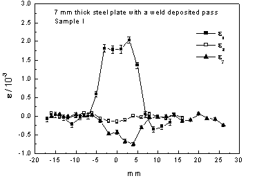
Fig. 4. Strain components as obtained in the first sample.
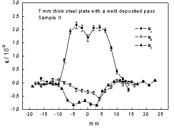
Fig. 5. Strain components as obtained in the second
sample.
Acknowledgement
This
study was supported by the research projects MSM2672244501, GA-CR 202/03/0891 and K1010104.
[1] I. C. Noyan and J. B. Cohen, Residual Stress - Measurement by Diffraction and Interpretation Springer-Verlag, New York, (1987).
[2] A. D. Krawitz, Introduction to Diffraction in Materials Science and Engineering, John Wiley & Sons, 2001.
[3] Alain Lodini, Michael Fitzpatrick (Eds.), Analysis of Residual Stress by Diffraction using Neutron and Synchrotron Radiation, Taylor and Francis, 2003.
[4] P. Mikula, M. Vrána, P. Lukáš, J. Šaroun, and V. Wagner, Mat. Sc. Forum 228-231 (1996) 269-274.
[5] P. Mikula, M. Vrána, P. Lukáš, J. Šaroun, P. Strunz, H.J. Ullrich, and V. Wagner, Proc. of the 5th Int. Conf.on Residual Stresses ICRS-5, June 16-18, 1997, Linköping, eds. T. Ericsson, M. Odén and A. Andersson, Vol. 2, p. 721-725.
[6] http://omega.ujf.cas.cz/